Hardware Switch Architectures for ATM Networks
In ATM networks, information is segmented into fixed-length cells, and cells are asynchronously transmitted through the network. To match the transmission speed of the network links and to minimize the protocol processing overhead, ATM performs the switching of cells in hardware-switching fabrics, unlike traditional packet switching networks, where switching is largely performed in software.
A large number of designs has been proposed and implemented for ATM switches (14). Although many differences exist, ATM switch architectures can be broadly classified into two categories: asynchronous time division (ATD) and space-division architectures.
Asynchronous Time Division Switches. The ATD, or single path, architectures provide a single, multiplexed path through the ATM switch for all cells. Typically a bus or ring is used. Figure 9 shows the basic structure of the ATM switch proposed in (15). In Fig. 6, four input ports are connected to four output ports by a timedivision multiplexing (TDM) bus.
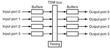
Figure 9. A 4 x 4 asynchronous time division switch
Each input port is allocated a fixed time slot on the TDM bus, and the bus is designated to operate at a speed equal to the sum of the incoming bit rates at all input ports. The TDM slot sizes are fixed and equal in length to the time it takes to transmit one ATM cell. Thus, during one TDM cycle, the four input ports can transfer four ATM cells to four output ports.
In ATD switches, the maximum throughput is determined by a single, multiplexed path. Switches with N input ports and N output ports must run at a rate N times faster than the transmission links. Therefore, the total throughput of ATD ATM switches is bounded by the current capabilities of device logic technology. Commercial examples of ATD switches are the Fore Systems ASX switch and Digital’s VNswitch
Space-Division Switches. To eliminate the single-path limitation and increase total throughput, space-division ATM switches implement multiple paths through switching fabrics. Most space-division switches are based on multistage interconnection networks, where small switching elements (usually 2 x 2 cross-point switches) are organized into stages and provide multiple paths through a switching fabric. Rather than being multiplexed onto a single path, ATM cells are space switched through the fabric. Three typical types of spacedivision switches are described next.
Banyan Switches. Banyan switches are examples of space-division switches. An N x N Banyan switch is constructed by arranging a number of binary switching elements into several stages (log2N stages). Figure 10 depicts an 8 x 8 self-routing Banyan switch (14). The switch fabric is composed of twelve 2 x 2 switching elements assembled into three stages. From any of the eight input ports, it is possible to reach all the eight output ports.
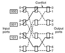
Figure 10. A 8 x 8 Banyan switch with binary switching elements
One desirable characteristic of the Banyan switch is that it is self-routing. Because each cross-point switch has only two output lines, only one bit is required to specify the correct output path. Very simply, if the desired output addresses of a ATM cell is stored in the cell header in binary code, routing decisions for the cell can be made at each cross-point switch by examining the appropriate bit of the destination address.
Although the Banyan switch is simple and possesses attractive features such as modularity, which makes it suitable for VLSI implementation, it also has some disadvantages. One of its disadvantages is that it is internally blocking. In other words, cells destined for different output ports may contend for a common link within the switch. This results in blocking all cells that wish to use that link, except for one. Hence, the Banyan switch is referred to as a blocking switch.
In Fig. 10, three cells are shown arriving on input ports 1, 3, and 4 with destination port addresses of 0, 1, and 5, respectively. The cell destined for output port 0 and the cell destined for output port 1 end up contending for the link between the second and third stages. As a result, only one of them (the cell from input port 1 in this example) actually reaches its destination (output port 0), while the other is blocked.
Batcher-Banyan Switches. Another example of spacedivision switches is the Batcher-Banyan switch (14). (See Fig. 11.) It consists of two multistage interconnection networks: a Banyan self-routing network and a Batcher sorting network. In the Batcher-Banyan switch, the incoming cells first enter the sorting network, which takes the cells and sorts them into ascending order according to their output addresses. Cells then enter the Banyan network, which routes the cells to their correct output ports.
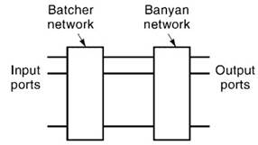
Figure 11. Batcher–Banyan switch
As shown earlier, the Banyan switch is internally blocking. However, the Banyan switch possesses an interesting feature. Namely, internal blocking can be avoided if the cells arriving at the Banyan switch’s input ports are sorted in ascending order by their destination addresses. The Batcher-Banyan switch takes advantage of this fact and uses the Batcher soring network to sort the cells, thereby making the Batcher-Banyan switch internally nonblocking. The Starlite switch, designed by Bellcore, is based on the Batcher-Banyan architecture (16).
Crossbar Switches. The crossbar switch interconnects N inputs and N outputs into a fully meshed topology; that is, there are N2 cross points within the switch (14). (See Fig. 12.) Because it is always possible to establish a connection between any arbitrary input and output pair, internal blocking is impossible in a crossbar switch.
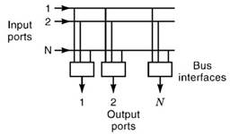
Figure 12. A knockout (crossbar) switch
The architecture of the crossbar switch has some advantages. First, it uses a simple two-state cross-point switch (open and connected state), which is easy to implement. Second, the modularity of the switch design allows simple expansion. One can build a larger switch by simply adding more cross-point switches. Lastly, compared to Banyan- based switches, the crossbar switch design results in low transfer latency, because it has the smallest number of connecting points between input and output ports. One disadvantage to this design, however, is the fact that it uses the maximum number of cross points (cross-point switches) needed to implement an N x N switch.
The knockout switch by AT&T Bell Labs is a nonblocking switch based on the crossbar design (17,18). It has N inputs and N outputs and consists of a crossbar-based switch with a bus interface module at each output (Fig. 12).
Nonblocking Buffered Switches. Although some switches such as Batcher-Banyan and crossbar switches are internally nonblocking, two or more cells may still contend for the same output port in a nonblocking switch, resulting in the dropping of all but one cell. In order to prevent such loss, the buffering of cells by the switch is necessary.
Figure 13 illustrates that buffers may be placed (1) in the inputs to the switch, (2) in the outputs to the switch, or (3) within the switching fabric itself, as a shared buffer (14). Some switches put buffers in both the input and output ports of a switch.
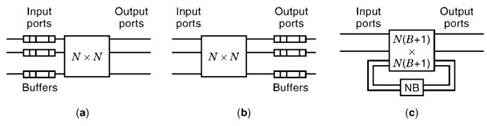
Figure 13. Nonblocking buffered switches
The first approach to eliminating output contention is to place buffers in the output ports of the switch (14). In the worst case, cells arriving simultaneously at all input ports can be destined for a single output port. To ensure that no cells are lost in this case, the cell transfer must be performed at N times the speed of the input links, and the switch must be able to write N cells into the output buffer during one cell transmission time. Examples of output buffered switches include the knockout switch by AT&T Bell Labs, the Siemens & Newbridge MainStreetXpress switches, the ATML’s VIRATA switch, and Bay Networks’ Lattis switch.
The second approach to buffering in ATM switches is to place the buffers in the input ports of the switch (14). Each input has a dedicated buffer, and cells that would otherwise be blocked at the output ports of the switch are stored in input buffers. Commercial examples of switches with input buffers as well as output buffers are IBM’s 8285 Nways switches, and Cisco’s Lightstream 2020 switches.
A third approach is to use a shared buffer within the switch fabric. In a shared buffer switch, there is no buffer at the input or output ports (14). Arriving cells are immediately injected into the switch. When output contention happens, the winning cell goes through the switch, while the losing cells are stored for later transmission in a shared buffer common to all of the input ports. Cells just arriving at the switch join buffered cells in competition for available outputs. Because more cells are available to select from, it is possible that fewer output ports will be idle when using the shared buffer scheme.
Thus, the shared buffer switch can achieve high throughput. However, one drawback is that cells may be delivered out of sequence because cells that arrived more recently may win over buffered cells during contention (19). Another drawback is the increase in the number of input and output ports internal to the switch. The Starlite switch with trap by Bellcore is an example of the shared buffer switch architecture (16). Other examples of shared buffer switches include Cisco’s Lightstream 1010 switches, IBM’s Prizma switches, Hitachi’s 5001 switches, and Lucent’s ATM cell switches.
Bibliography:
1. CCITT Recommendation I-Series. Geneva: International Telephone and Telegraph Consultative Committee.
2. J. B. Kim, T. Suda and M. Yoshimura, International standardization of B-ISDN, Comput. Networks ISDN Syst., 27: 1994.
3. CCITT Recommendation G-Series. Geneva: International Telephone and Telegraph Consultative Committee.
4. ATM Forum Technical Specifications [Online]. Available www: www.atmforum.com
5. Report of ANSI T1S1.5/91-292, Simple and Efficient Adaptation Layer (SEAL), August 1991.
6. Report of ANSI T1S1.5/91-449, AAL5—A New High Speed Data Transfer, November 1991.
7. CCITT Recommendation Q-Series. Geneva: International Telephone and Telegraph Consultative Committee.
8. J. Bae and T. Suda, Survey of traffic control schemes and protocols in ATM networks, Proc. IEEE, 79: 1991.
9. B. J. Vickers et al., Congestion control and resource management in diverse ATM environments, IECEJ J., J76-B-I (11): 1993.
10. J. S. Turner, New directions in communications (or which way to the information age?), IEEE Commun. Mag., 25 (10): 1986.
11. G. Gallassi, G. Rigolio, and L. Fratta, ATM: Bandwidth assignment and bandwidth enforcement policies. Proc. GLOBECOM’89.
12. ATM Forum, ATM Forum Traffic management specification version 4.0, af-tm-0056.000, April 1996, Mountain View, CA: ATM Forum.
13. Quantum Flow Control version 2.0, Flow Control Consortium, FCC-SPEC-95-1, [Online], July 1995. http://www.qfc.org
14. Y. Oie et al., Survey of switching techniques in high-speed networks and their performance, Int. J. Satellite Commun., 9: 285-303, 1991.
15. M. De Prycker and M. De Somer, Performance of a service independent switching network with distributed control, IEEE J. Select. Areas Commun., 5: 1293-1301, 1987.
16. A. Huang and S. Knauer, Starlite: A wideband digital switch. Proc. IEEE GLOBECOM’84, 1984.
17. K. Y. Eng, A photonic knockout switch for high-speed packet networks, IEEEJ. Select. Areas Commun., 6:1107-1116,1988.
18. Y. S. Yeh, M. G. Hluchyj, and A. S. Acampora, The knockout switch: A simple, modular architecture for high-performance packet switching, IEEE J. Select. Areas Commun., 5: 12741283, 1987.
19. J. Y. Hui and E. Arthurs, A broadband packet switch for integrated transport, IEEE J. Select. Areas Commun., 5: 1264-1273, 1987.
20. ATM Forum, LAN emulation over ATM version 1.0. AF-LANE- 0021, 1995, Mountain View, CA: ATM Forum.
Date added: 2024-02-20; views: 810;