GPS Signal Evolution
Although the details of GPS signals are summarized in Section 3.7, this section summarizes their evolution, which also has driven the evolution of satellites, ground segment, and user equipment. The original GPS signals were the Coarse/Acquisition (C/A) signal and Precision (P) signal on Link 1 (L1) - a carrier frequency of 1575.42 MHz - and the P-signal on Link 2 (L2) - a carrier frequency of 1227.60 MHz. The first Block II satellite, launched in 1989, introduced the ability to transmit the encrypted (Y) version of the P-signal, known as the P(Y)-signal.
In 1998, the IGEB decided to add two new civil signals. The result was the L2 civil (L2C) signal at L2 and the L5-signal at a carrier frequency of Link 5 (1176.45 MHz).
Even the earliest GPS satellites were specified to be able to transmit either the P-signal or the C/A-signal on L2. When the decision was made to transmit both a civil signal and the P(Y)-signal on L2, the intent was merely to transmit a duplicate of the L1 C/A-signal on L2, in addition to P(Y)- signal. However, the C/A-signal’s design included several undesirable compromises.
Repetition of spreading codes within a data bit introduced issues with radio frequency interference, and the biphase transitions due to data message modulation disrupt long coherent integration times in receiver processing, making tracking of the signal more fragile. While these limitations were recognized at the time of the design, they were adopted in the C/A-signal design to simplify receiver processing. A third fundamental limitation of the C/A- signal is the rigid structure of the data message, which does not allow adaptation as needs change.
The GPS program office agreed to adopt a modified C/A- signal design for the L2 civil signal, as long as the changes had minimal impact on satellite cost and schedule. Thus, the BPSK-R(1) spreading modulation was maintained, but time division multiplexed pilot and data components were introduced, with longer spreading codes. A flexible data message design was also introduced. Unfortunately, the aviation community eschewed the L2C-signal since it was not in an ITU-protected Aeronautical Radio Navigation Service (ARNS) frequency band.
Subsequently, the L5-signal was designed, with primary emphasis on its ability to meet the needs of civil aviation. The history of its development is summarized in [22]; its design includes a spreading modulation like that of P(Y)- signal, pilot and data components in phase quadrature, and a flexible data message turned to the needs of civil aviation.
Almost in parallel, a new military signal was being designed to overcome the projected inherent limitations of the P(Y)-signal. This signal, to be known as the M-signal, or military signal, uses the BOC spreading modulation invented to concentrate the signal’s power at frequencies away from those used by civil signals sharing the same center frequency.
The fourth civil signal and eighth GPS signal, L1C, resulted from political considerations. As the United States and European Community negotiated concerning GPS and Galileo in the 2002 through 2004 time frame, European representatives encouraged the United States to adopt a civil signal at 1575.42 MHz - the frequency that GPS calls L1 and Galileo calls E1 - that would have common characteristics with the corresponding Galileo signal.
The United States committed to this in the 2004 agreement, opening the possibility for a modernized GPS civil signal in the most commonly used frequency band. After the agreement, European experts proposed changes to the commonly adopted BOC(1,1) spreading modulation, but US experts disapproved of these proposed changes. Finally, the United States proposed an improved spreading modulation that was mutually acceptable, and it was jointly refined and adopted. The result is a common spectrum shape, although the GPS and Galileo signals differ in the waveforms that are used, and in many other aspects of their signal designs.
The received power of GPS signals continues to evolve. In the early 2000s, the specified minimum received power of C/A-signals and P(Y)-signals was increased by 1.5 dB to accommodate increased interference as GPS shared spectrum with other satnav systems; this was a “paper” power increase effected by reducing the excess atmospheric loss in link budget calculations. Actual increases in minimum received power have occurred for some signals with Block IIF satellites, and will occur for L2C-, L2P(Y)-, L5-, and both M-signals with GPS III satellites, compared to Block II satellites.
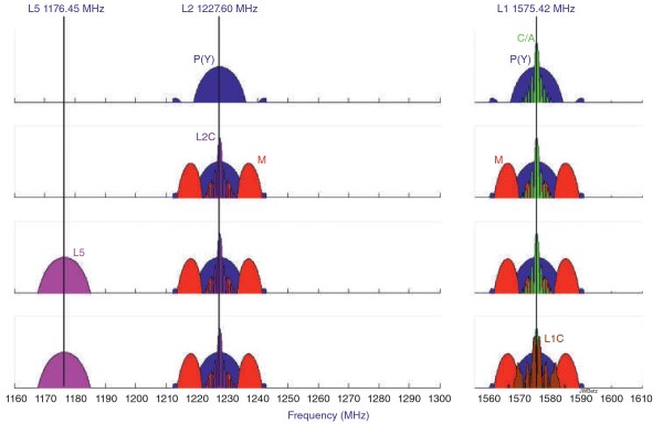
Figure 3.1. Modernization of GPS signals. Source: Reproduced with permission of John Wiley & Sons
Figure 3.1 depicts the evolution in GPS signals, accompanied by the satellites that implement the changes. In this graphic, the power spectral densities are all portrayed at the same power, not reflecting the actual different received power levels of the different signals.
Date added: 2024-08-26; views: 618;