Augmentation Systems
Over the past two decades, augmentation systems have provided tremendous enhancements to satnav. The most widely used augmentation around the world is assisted satnav, or A-satnav, described in [5] and Chapter 24 of [3] and depicted in Figure 2.9. Using infrastructure that reads data messages from all broadcast signals, A-satnav provides the needed information via communications links to a satnav receiver integrated with a communications system - typically a commercial wireless network.
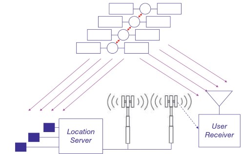
Figure 2.9. Assisted satnav [3]. Source: Reproduced with permission of IEEE
The receiver then need not perform much of the relatively fragile and time-consuming process of reading information from each broadcast signal’s data message, although the time of transmission maybe needed. Furthermore, the communications network can also provide a frequency reference and time reference to the receiver, allowing it to reduce the uncertainty region over which it needs to search for signals. The result of A-satnav is a much faster time to first fix, along with positioning under challenging conditions, such as indoors, where stand-alone satnav reception would not function.
A second type of augmentation system, known as Satellite-Based Augmentation System (SBAS), was developed to enable greater reliance on satnav for aviation safety of life. As shown in Figure 2.10, SBAS uses reference stations dispersed over the service region, which may be the size of a continent or larger. Receivers at these reference stations, whose antennas are in precisely surveyed locations, read the data messages from broadcast signals and measure the quality of the broadcast signals, while performing code tracking to measure pseudoranges to the satellites.
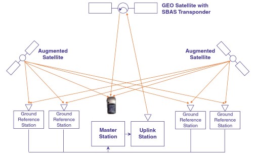
Figure 2.10. Satellite-Based Augmentation System [3]. Source: Reproduced with permission of IEEE
This information is passed to a master station, which computes the errors between the measured pseudoranges and the true pseudoranges between the satellites and the known receiver antenna locations, as well as ionospheric delays using dual-frequency, ionosphere-free, measurements [3].
If a signal’s data message, signal quality, or pseudorange error is unacceptable, the master station determines that there is a loss of integrity in that signal. In addition, the master station uses many measurements to attribute the errors to ionospheric delay, broadcast clock corrections, and broadcast ephemeris. The master station constructs augmentation messages containing a map of ionospheric delays, indicators of each signal’s integrity, and corrections to each signal’s broadcast clock corrections and ephemeris.
The augmentation messages are passed to an uplink station that forms a signal modulated by the augmentation message, and transmits this signal (typically at C band, K band, or Ku band) to a transponder on a geostationary satellite. The transponder frequency shifts the signal to an L-band frequency, amplifies it, and broadcasts it toward Earth. Receivers use the augmentation message to determine if satnav signals have adequate integrity, and also to correct measurements made with the satnav signals. Although SBAS signals are primarily communications signals, in some cases the receiver can also make measurements using them.
The third type of augmentation system, shown in Figure 2.11, makes differential measurements between a user receiver, or rover, and a reference receiver or network of reference receivers that are accurately surveyed to known locations. The rover uses code or carrier phase measurements, along with information transmitted via a communications link from the reference receiver or network, to accurately determine the rover receiver’s location relative to the reference.
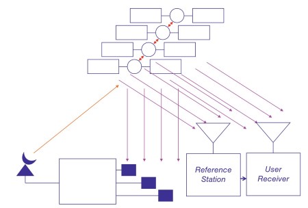
Figure 2.11. Differential satnav [3]. Source: Reproduced with permission of IEEE
When the reference and rover receivers make measurements on the same satellites, the rover can compute differences between pairs of measurements in ways that remove many sources of error. Decimeter accuracies can be obtained using code measurements, and centimeter accuracies can be obtained using carrier phase measurements, once the carrier phase ambiguities have been removed.
Date added: 2024-08-26; views: 619;