Acoustic Elements in Runner Systems. Acoustic Measurement and Simulation Tools
A variety of acoustic principles can be used to attenuate intake noises; see Fig. 7-284. The most important damper design is constructed in principle like a so-called series resonator. This is a system taking the form of a Helmholtz resonator, in which a damping chamber is connected to a section of tubing.
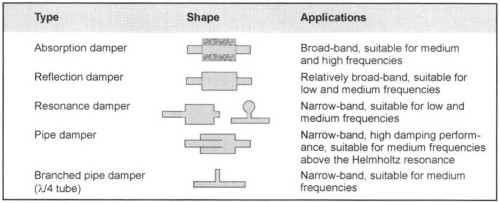
Fig. 7-284. Construction forms for acoustic dampers and their application range
A resonator such as this functions in principle like a sprung mass system in which the spring is represented by the compressible air in the chamber, the mass, on the other hand, by the air pulses in the pipe. Depending on its dimensions, a resonance frequency f0 can be calculated at which a resonator such as this amplifies the sound introduced. The following formula is used to calculate the frequency:
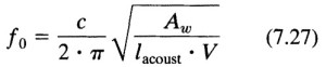
where Aw is the mean cross section of the resonator throat, lacoust effective length of the throat, and V the volume of the chamber. Inversely, frequencies upward of fo x √2 are damped. The objective is to use this phenomenon in the damper filter. In order to achieve the best possible damping, fo has to be as low as possible, meaning well below the frequencies occurring during operation.
This can be achieved by increasing the volume of the air filter body, by reducing the intake cross section or by lengthening the intake snout. Because of the fact that the installation size is usually limited, the volume of the body cannot be increased at will. A severely reduced intake cross section also has undesirable side effects since the flow of intake air is throttled. Increased pressure loss always means a loss of engine performance, which is why in practice the pressure loss in the intake tube is kept in bounds by designing a diffuserlike intake opening, similar to a Venturi tube.
Lengthening the intake tube also runs into system-imposed limits, while a corrective measure such as this also harbors the hazard of tube resonances that can counteract damping at certain frequencies. That is why exact tuning of the entire system is needed to identify the ideal compromise between expense and profitability.
Acoustic Measurement and Simulation Tools. Many tools are available for use in designing an intake system; the simulation tools, in particular, have grown in significance in recent years since they can be used to predict acoustic properties even in a very early development stage. In addition to the finite element method, 1-D calculation programs based on the transfer matrix method or the finite differences method have become established here.
The latter offers the advantage that, in addition to the acoustic values, thermodynamic values can also be calculated. The calculation results can be validated at simple component test beds as soon as initial samples are available. Final optimization with parts close to the mass-production components is then carried out on the engine acoustic test bed or in the vehicle.
In addition to the pure reduction of the acoustic pressure level, the quality of the noise is playing an even more important part in development. Here “dummy head” recordings are used to log the noises that are then evaluated subjectively by test persons in comparison listening tests. These tools are shown in Fig. 7-285.
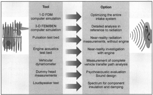
Fig. 7-285. Acoustic measurement and simulation tools
Future Systems. In addition to passive measures, adaptive measures are employed more and more in intake systems. Active manifolds are used primarily to increase the airflow rate. But in the air routing systems, too, these components can be employed to optimize acoustic properties.
Thus, for example, by using a single-stage, active manifold in the lower speed range, when the engine does not require its full volumetric flow, a smaller intake cross section can be used in order to achieve low frequency tuning of the Helmholtz resonator. Figure 7-286 shows such a configuration as an example.
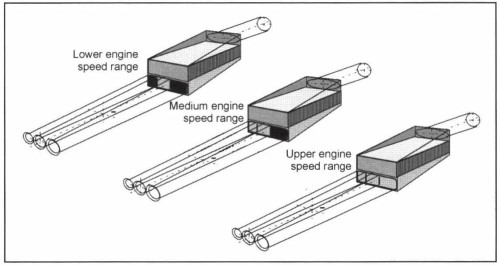
Fig. 7-286. Multistage, active intake manifold
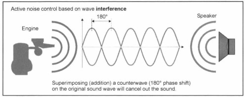
Fig. 7-287. Active noise control
The advent of electronics in the intake system has paved the way for entirely different system designs, such as the use of inverted or dephased sound to cancel out noise. If the noise arriving from the engine is countered by a wave of the same amplitude but 180° out of phase, then these two waves cancel each other out. This principle is also known as active noise control and is depicted in Fig. 7-287.
Bibliography: [1] Müller, K., and W. Mayer, Einfluss der Ventilgeometrie auf das Einströmverhalten in den Brennraum, 3rd edition, Vieweg, Wiesbaden, 1999.
[2] Wild, S., "Torque vs. Power—No Conflict with Highly Variable Resonance Runners," Global Powertrain Congress, Detroit, 2001.
[3] Weber, O., and St. Wild, "Leistung plus Drehmoment–optimierte Sauganlage mit voll variablen Resonanzrohren," 22nd International Vienna Engine Symposium, 2001, VDI Fortschrittsberichte, Series 12, No. 455, Vol. 2, pp. 320–332.
[4] Alex, M., Akustikoptimierung bei der Filterentwicklung, Haus der Technik, Essen, 1996.
[5] Weber, O., "topsys–A New Concept for Intake Systems," SAE 98 "Merra."
[6] Weber, O., H. Paffrath, H. Beutnagel, and W. Cedzich, "Thermo-dynamische und akustische Auslegung von Ansaugsystemen für Fahrzeugmotoren unter Berücksichtigung fertigungstechnischer Belange," 19th International Vienna Engine Symposium, May 1998.
Date added: 2024-07-30; views: 683;