Intake Systems. Thermodynamics in Air Intake Systems
The air intake systems in modem internal combustion engines serve a number of functions in addition to routing and filtering the combustion air. The demands placed on intake systems continue to rise with increasing engine complexity. Two major trends are emerging.
System Competence. The entire air routing configuration is seen as a system extending from the intake opening to the cylinder head; it is engineered and manufactured by the supplier and delivered ready for installation. This presumes that the supplier will fully understand the system, going beyond the air supply system proper and including the exhaust system in view of the exchange of gases in the cylinder.
Modularization. A second trend is the increasing modularity of the intake system. A modular design makes good sense since the air supply system is spread out all around the engine and, simply because of its size, lends itself to the attachment of discrete components. These components are not necessary components of the air management system proper.
One example is locating the motor management circuitry inside the air filter; passing air is used to cool the electronics. Modularization requires, in addition to an understanding of the system as a whole, increased competency in manufacturing and integration.
Figure 7-274 schematically shows the air path in a four-cylinder engine together with the main functions and some of the attached components. The thermodynamic situation along the air path is explained below along with the proximity to the fields of acoustics and filtration.
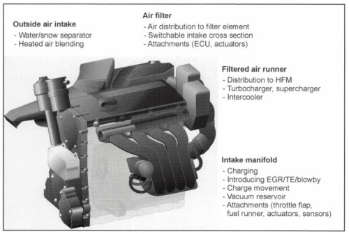
Fig. 7-274. Air flow system for an internal combustion engine (schematic)
Thermodynamics in Air Intake Systems. The thermodynamics in the air supply system depends on the combustion process (gasoline or diesel) and on the charging principle. The external air piping and air filter are similar in all the variants. The systems differ markedly, however, downstream from the air filter, depending on the charging principle; see Fig. 7-275.
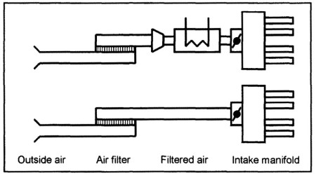
Fig. 7-275. Air path for naturally aspirated engines (below) and for turbocharged engines (above)
Turbocharged engines are fitted with an elaborate clean-air section with a compressor and aftercooler, while the intake manifold is simple in design, as it serves primarily to distribute air to the cylinders.
Naturally aspirated engines, by contrast, have a simple clean-air section but in most cases complex, active intake manifolds to improve cylinder fill.
External Air Section. The external air path, i.e., the section of the intake system between the intake opening and the air filter, not only guides the air but also is used for the addition of warm air and the elimination of dirt. Blending in warm air influences the engine’s operating properties, particularly in the cold starting phase. This function grows in significance in the future as more stringent limit values are adopted in exhaust gas legislation.
Drying the filter element and thawing snow are further reasons for adding warm air. Fuel consumption can be favorably influenced by intelligent temperature regulation for the intake air. Warm air is drawn in through a second take-up point near the exhaust manifold; it is activated by flaps. The flaps are actuated by thermostat elements or by vacuum or electrical actuators.
A suitable external air routing system also separates coarse particles (droplets, snow, dirt) with minimal pressure loss by bends. This preliminary separation helps to keep down the amount of grime collected at the air filter and protects the filter element against moisture. Particle separation and pressure loss at diversion points are determined in advance with the help of CFD.
Air Filter Body. What might colloquially be referred to as the “air filter” or “air cleaner” comprises the filter element, the air cleaner body, and the cover. In addition to its acoustic effect, the body serves to optimize the airflow path and air distribution around the filter proper. The ideal here is the most uniform distribution possible.
Air velocity perpendicular to the filter element has to be homogeneous over the entire filter surface area. When the arrival of the air is not uniform, there is greater pressure loss at the filter element, and engine efficiency is degraded. The dirt and dust trapping capacity of the filter material is also optimized with homogeneous airflow.
Three-dimensional CFD techniques are employed at a very early stage to engineer the airflow in air filter bodies, Fig. 7-276. This makes it possible to determine the ideal geometry very early and with a minimum of effort for physical testing.
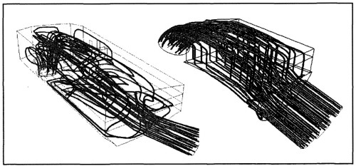
Fig. 7-276. Airflow to the filter elements: Not uniform and with great pressure drop (left); nearly ideal (right)
In one example, it was possible to reduce physical size by 30% with the same pressure loss level and dust capacity. It was possible to attain air distribution that was within 3% of the ideal test bed value.
Clean-Air Channel. The air impinging on the mass flow meter that measures the intake air on the clean-air side is analyzed for new intake systems, using CFD simulation, in order to achieve uniform flow. In view of more stringent emission limits, reliable functioning of this meter, in all operating states and for the life of the vehicle, is specified. Gradual degradation of the meter resulting from deposits on the sensor (oil droplets from the crankcase or from the exhaust gas return system) can also be reduced dramatically by applying CFD simulation to the air flow path.
The gas pulsations generated by the engine become more intensive downstream on the clean-air side. If thermodynamics and acoustics are not seen as a whole, then this has to be done at the latest in the clean-air runner since both disciplines exert an effect on air routing. In the area associated with the clean-air runner one finds acoustic components (shunt resonators, λ/4 tubes) that also have an influence on gas exchange in the cylinders.
Today simulation tools are used for such components. The airflow rate and noise at the inlet tube are thus calculated at a very early point in the design phase. The effort required for modeling can be significantly reduced since a single calculation model delivers both results.
Supercharged and turbocharged engines have a longer airflow path than naturally aspirated engines. In engines with a turbocharger, the intake air passes from the forward module and through the air filter to the compressor located near the exhaust manifold. The compressed air is then returned to the forward module, where the aftercooler is located. Finally, the clean-air runner terminates at the intake manifold at the engine.
Intake Systems. Engines with mechanical superchargers or exhaust-driven turbochargers require intake manifolds and runners to distribute the combustion air to the cylinders. The aim here is to achieve short intake runners with little pressure loss and good uniformity of distribution to the cylinders.
Naturally aspirated engines use the wave effects initiated by the piston to compress intake air. The procedure known as “resonance tube charging” is described in Fig. 7-277.
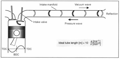
Fig. 2-277. Principle of resonance tube charging
When the intake valve is opened, the piston, as it moves downward, creates a vacuum “wave” that moves opposite the direction of airflow, away from the combustion chamber and along the resonance tube. The vacuum wave is reflected at the collector, because of a change in cross section. The pressure wave moving back toward the combustion chamber can be utilized to improve cylinder filling, provided that it arrives before the intake valve closes.
Ideal tube length, at constant speed of sound a, is inversely proportional to engine speed n. To achieve good cylinder fill over a broad engine speed range, all vehicle classes are seeing an increasing use of intake manifolds that can alternate between short and long resonance tubes. A typical response curve for an active intake manifold with two resonance tube lengths is shown in Fig. 7-278.
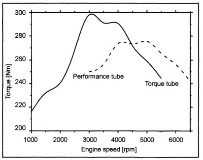
Fig. 7-278. Torque progression in a six-cylinder engine with active intake manifold
With increasing intake system complexity, the increase in the airflow rate depends more and more on the quality of the manufacturing and materials. Figure 7-279 uses gasket quality to illustrate the sensitivity of airflow rate to leakage. A gasket that permits an increase in the airflow rate in a two-stage active manifold can in three- and four-stage manifolds quite conceivably lead to a reduction of the airflow rate.
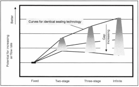
Fig. 7-279. The influence of selector flap gasket technology on air flow rate
In addition to leakage through the switching elements, there is a series of other variables that influence the change of gases in the intake manifold. Figure 7-280 provides a survey of potential sources of loss.
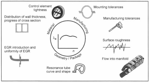
Fig. 7-280. Factors influencing the air flow rate for active intake manifolds
This makes it necessary for suppliers of modem intake systems to define the entire intake system in both thermodynamic and mechanical terms at a very early point in development work. This requires linking and networking all the CAE tools right from the outset of the development project.
Date added: 2024-07-30; views: 712;