Basic Measurements. Unified distances between axes for factory and industrial premises and accommodation
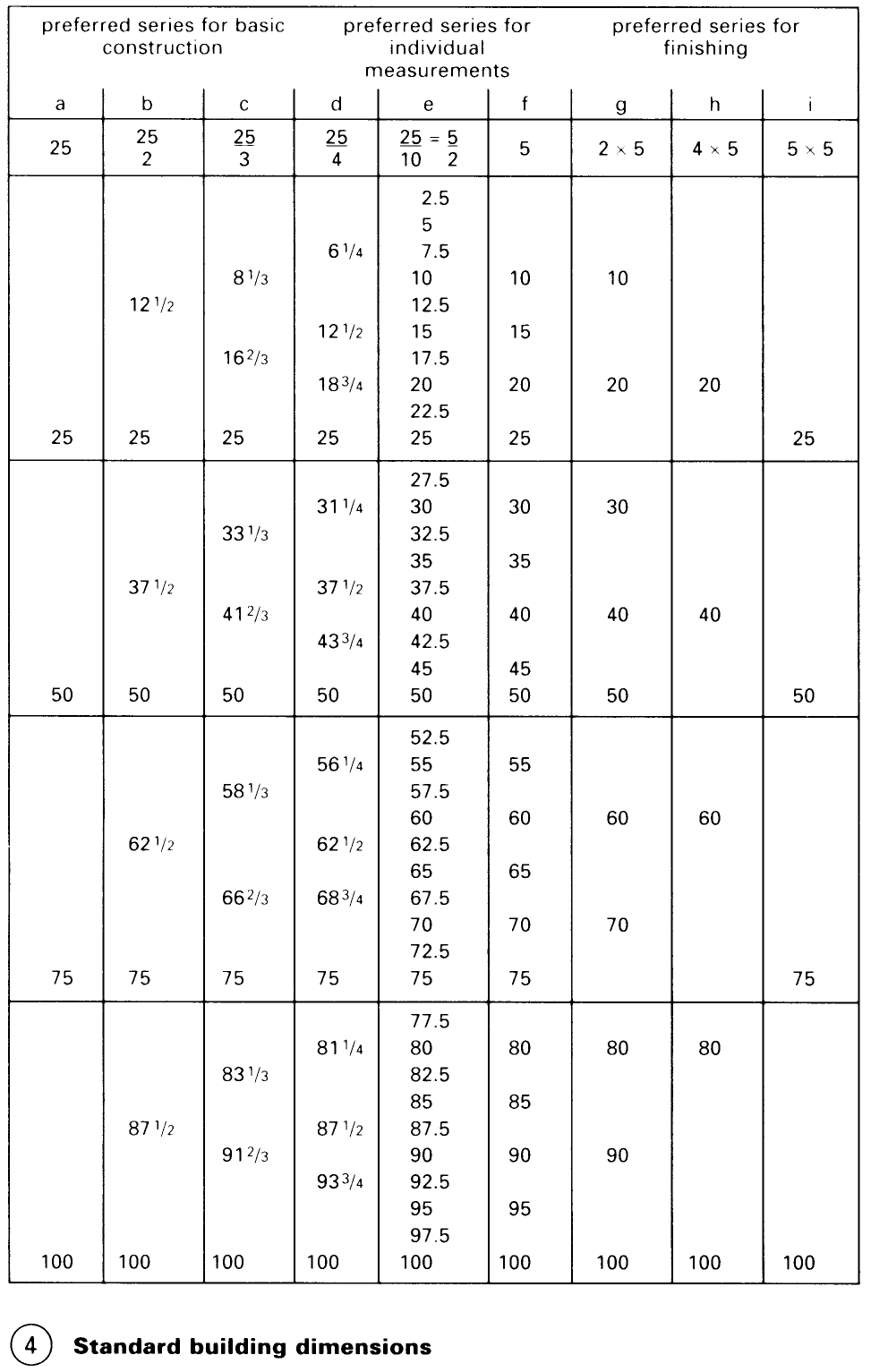
Individual (mostly small) dimensions are used for details of basic construction/finishing (e.g., thickness of joints/ plaster, dimensions of rebates, wall fixings/tolerances). Basic structural measurements relate, for example, to masonry (excluding plaster thicknesses), structural floor thicknesses, unplastered doors and window openings. Finished measurements refer to the finished building (e.g. net measurements of surface finished rooms and openings, net areas and finished floor levels).
For building construction without joints, nominal dimensions equal the standard dimensions; with joints, the allowance for the joint is subtracted: e.g. building brick nominal length = standard length (250mm) - thickness of intermediate joint (10mm) = 240mm; nominal thickness of in-situ concrete walls = standard thickness = 250mm. In accordance with the standard number and measurement systems, small dimensions (<25mm), are chosen (in mm) as: 25, 20, 16,12.5, 10, 8, 6.3, 5, 3.2, 2.5, 2, 1.6, 1.25, 1.
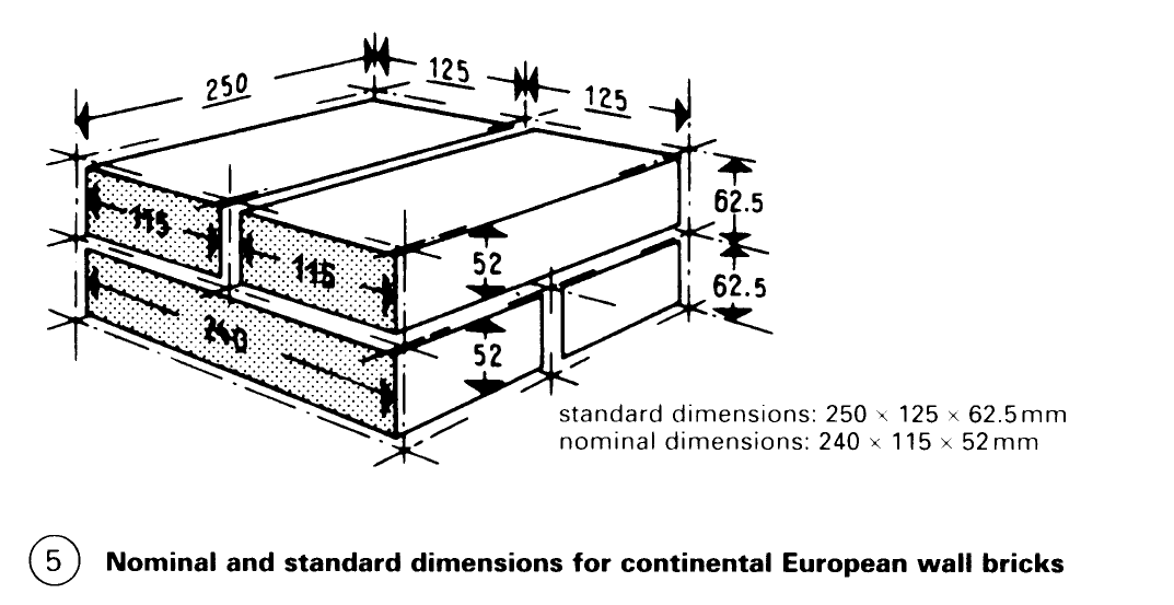
In many European countries, even small structural components conform with the standard building numbering system, e.g. standardised building bricks. A nominal brick dimension of 240x115mm reconciles the old non-metric format (250x120mm or 260x130mm with joints) with the new standard (250x125mm with joints). With the appropriate height, with joint, of 62.5mm (nominal brick dimension = 52mm), this gives an aspect ratio of 250x125x62.5 - 4:2:1. – (4).
Other basic construction component dimensions (e.g. concrete blocks p. 63, window and door openings p. 176-87 and floor levels) are similarly aligned, so these numerical values reoccur. The UK brickwork dimensions differ: in the past, large variations in the size of ordinary fired clay products often led to critical problems when bonding clay bricks; now, BS 3921: 1895 provides one standard for dimensioning (- (5): coordinating size (225x 112.5x75mm, including 10mm in each direction for joints and tolerances), and the relating work size (215 (2 headers plus 1 joint) x 102.5 x 65mm).
Japan has the oldest building size regulations where, following the great fire in Tokyo in 1657, the style and size of houses were laid down on the basis of systematic measurement according to the 'Kiwariho method'. The basic dimension was the Ken = 6 Japanese feet = 1.818m. The distances between the wall axes were measured in half or whole Ken, windows doors and even mat sizes were determined on this basis, which considerably simplified house building in Japan, making it quicker and cheaper. Examples -> BOL.
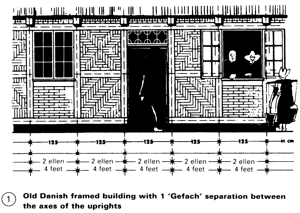
In Germany, a similar system was developed in the area of half-timbered construction, prior to the introduction of the metre. The determining unit was the Prussian foot, which was most widely propagated and corresponded to the Rhenish and Danish foot.
The dimension between the axes of uprights was mostly 1 Gefach = 2 Ellen = 4 feet – (1). The Prussian, Rhenish and Danish foot, still in use in building practice in Denmark, is translated as 312.5mm, the Elle as 625mm and the Gefach as 1.25m, in the metric system. Private construction firms had adopted a similar system of 1.25m, for their system buildings, particularly for wood panel construction.
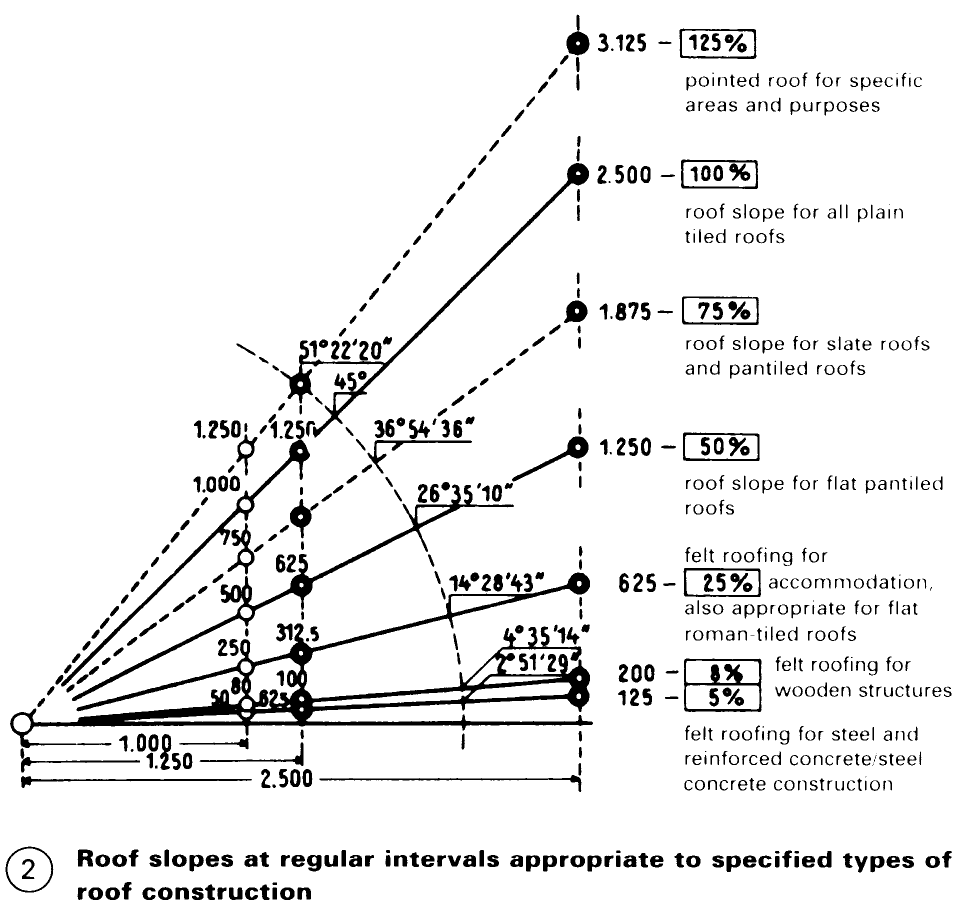
The UK and USA adopted a system of measurement based on 4 feet, which is close to 1.25m, with 4 English feet = 1.219m. Building panels (e.g. hardboard) manufactured on US machines are therefore 1.25m wide in countries using the metric system. German pumice boards for roofs also have the standard dimension of 2 x 1.25 = 2.50m, the same as plaster boards. Finally, 125 is the preferred number in the standard number system. The series of measurements resulting from 1.25m was standardised in Germany in 1942 with the corresponding roof slopes (2). In the meantime, thousands of types of structural components have been produced to this system of measurement. The distance between the axes of beams in finished ceilings today is, accordingly, usually 125/2 = 625mm = the length of the stride of a human adult -> p. 17.
Unified distances between axes for factory and industrial premises and accommodation. Industrial structures and structures for accommodation are mostly subdivided in plan into a series of axes at right angles. The line of measurement for these axes is always the axis of the structural system of the construction. The separations between axes are dimensional components of the plan, which determine the position of columns, supports, the centres of walls, etc. In the case of rigid frames, the centre axes of the bearing points of the foundations are decisive. The measurements are always referenced to the horizontal plan and vertical projection plane, even in the case of sloping roofs.
In industrial structures, a basic measurement of 2.5m applies to the spacing of axes. Multiples of this give axis spacing of 5.0, 7.5 and 10.0m, etc. In special cases (accommodation or slab structures), a basic measurement of 2.50/2 = 1.25m, or a multiple thereof, can be used. This results in intermediate dimensions of 1.25, 3.75, 6.25, 8.75m. However, so far as possible, these sub-dimensions should not be used above 10m.
Appropriate geometric steps over 10 m are recommended as follows: 12.50m, 15.00m, 20.00m, 25.00m, 30.00m, 40.00m, 50.00m, 60.00m, (62.50m), 80.00m, 100.00m.
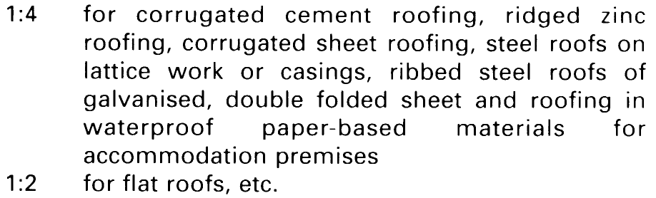
Roof slopes depend on the type of roofing and the subconstruction employed. The following roof slopes have been established to correspond with practical requirements:
- 1:20 for boarded roofing on steel and reinforced concrete structures and wood cement roofs, with the exception of special designs such as shell and saw-tooth roofs, etc.
- 1:12.5 for boarded roofing on wooden structures
The cited axis spacings influence the individual structural components: columns, walls, ceilings, trusses, purlins, rafters, roof planking, windows, glazing, doors, gates, crane runways and other elements. The establishment of a specified basic measurement for the spacing of axes creates the prerequisites for a hierarchical system of measurement standardisation for individual structural components and their matching interconnection. The spacings between axes are simply added together, without intermediate measurements. However, masonry, glass panes, reinforced concrete panels etc., must include an element for the jointing arrangements.
The points of support for a travelling crane can be unified on the basis of the standardised axis spacings.
The matched, standardised components and assemblies are interchangeable, can be prepared off-site and used in a versatile manner. Mass production, interchangeability of components/assemblies and the availability of standardised components and assemblies in store result in savings in work, materials, costs and time. The arrangement of the structural axes brings considerable simplification to building supervision.
Date added: 2023-01-01; views: 945;