Modular System. Geometric Considerations. Modular Arrangements in Building Practice
International agreements on the planning and execution of building work and for the design and manufacture of building components and semi-finished products are incorporated into national standards. The modular system is a means of coordinating the dimensions applicable to building work.
The term 'coordination' is the key, indicating that the modular layout involves an arrangement of dimensions and the spatial coordination of structural components. Therefore, the standards deal with geometrical and dimensional requirements. The modular system develops a method of design and construction which uses a coordinate system as a means of planning and executing building projects. A coordinate system is always related to specific objects.
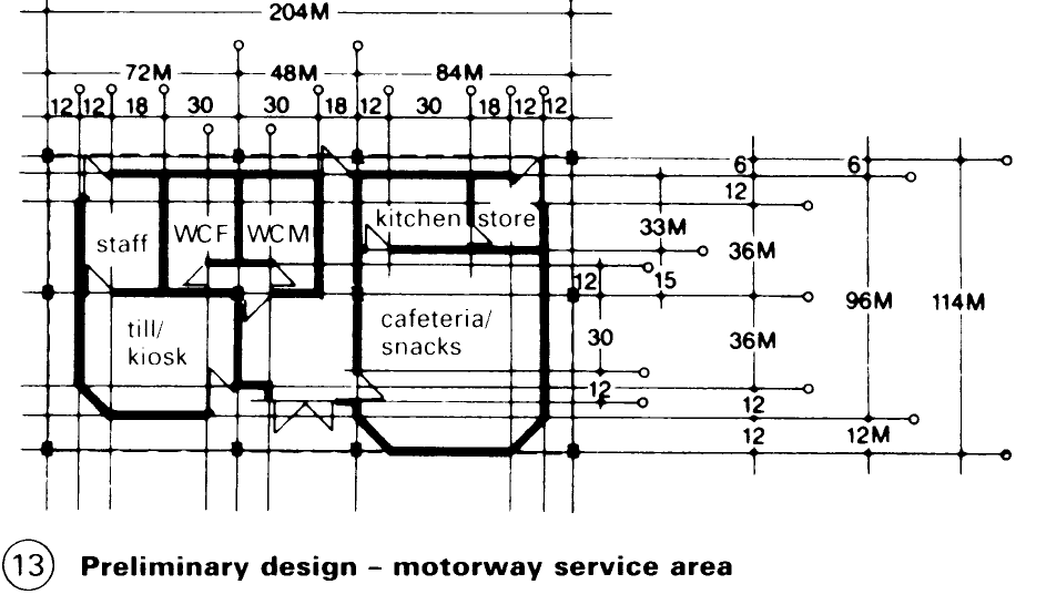
Geometric considerations. By means of the system of coordinates, buildings and components are arranged and their exact positions and sizes specified. The nominal dimensions of components as well as the dimensions of joints and interconnections can thereby be derived. – (1) – (6), (13).
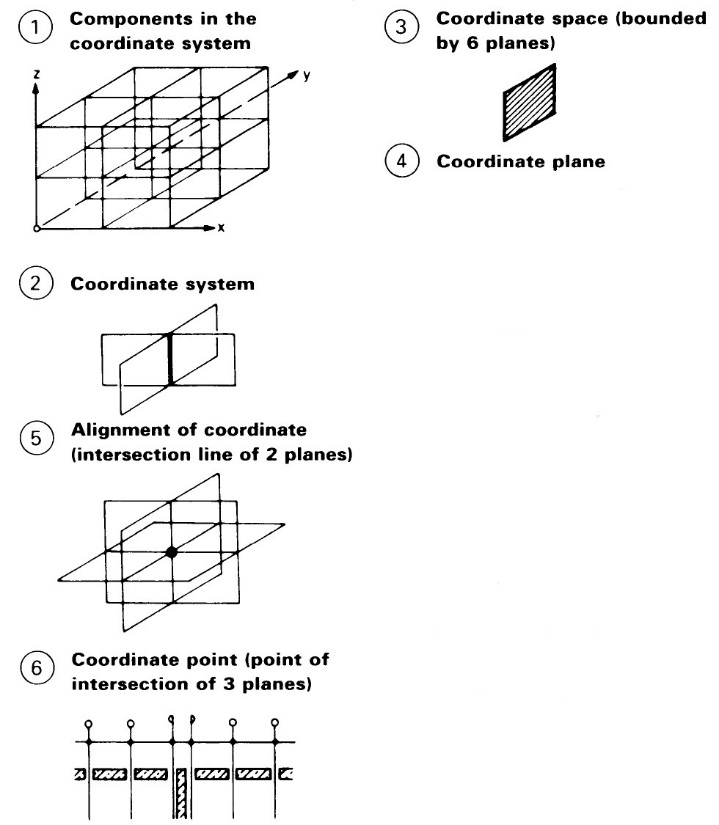
A coordinate system consists of planes at right angles to each other, spaced according to the coordinate measurements. Depending on the system, the planes can be different in size and in all three dimensions.
As a rule, components are arranged in one dimension between parallel coordinate planes so that they fill up the coordinate dimension, including the allowance allocated to the joints and also taking the tolerances into account. Hence a component can be specified in one dimension in terms of its size and position. This is referred to as boundary reference. - (7), (12).
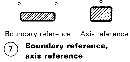
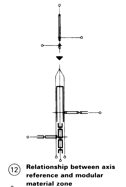
In other cases, it can be advantageous not to arrange a component between two planes, but rather to make the central axis coincide with one plane of the coordinate system. The component is initially specified in one dimension with reference to its axis, but in terms of position only.
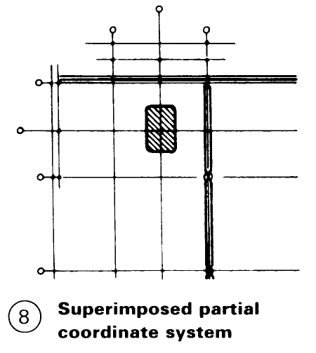
A coordinate system can be divided into sub-systems for different component groups, e.g. load-bearing structure, component demarcating space, etc. - (8).
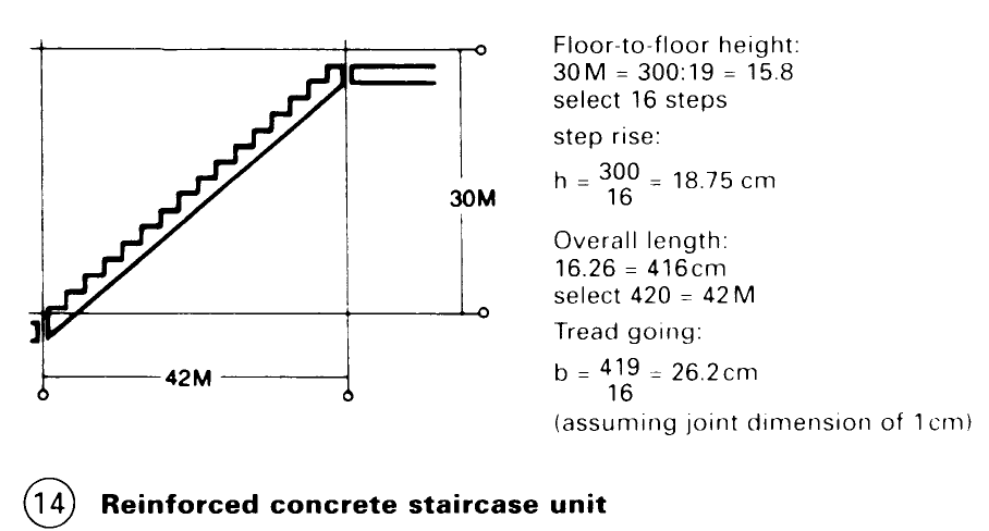
It has been established that individual components need not be modularised, e.g. individual steps on stairways, windows, doors, etc. (14)
For non-modular components which run along or across the whole building, a so-called 'non-modular' zone can be introduced, which divides the coordinate system into two- sub systems. The assumption is that the dimension of the component in the non-modular zone is already known at the time of setting out the coordinate system, since the nonmodular zone can only have completely specified dimensions. (9)

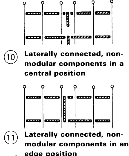
Further possible arrangements of non-modular components are the so-called centre position and edge position within modular zones. (10) – (11).
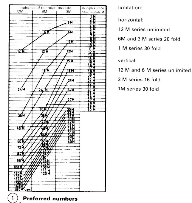
Modular Arrangements in Building Practice. The units for the modular arrangement are M = 100mm for the basic module and 3M = 300mm, 6M = 600mm, and 12M = 1200mm, for the multi-modules. The limited multiples of the preferred numerical series are generated in this way. The coordinate dimensions - theoretical standard dimensions - are, ideally, generated from these. These limitations are the result of functional, constructional and economic factors. – (1)
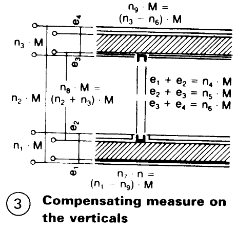
In addition, there are standardised, non-modular extending dimensions, I = 25mm, 50mm and 75mm, e.g., for matching and overlapping connection of components. – (3)
Date added: 2023-01-01; views: 769;