Metaloflex Layered Metal Head Gaskets
Multilayer steel gaskets have been used as head gaskets (Fig. 7-291) in mass production since 1992. Particularly in modem diesel engines and in high-performance gasoline engines, extreme effort is required to devise a solution suitable for mass production when using the elastomer seals employed up to that time.
The essential advantage of the layered metal head gaskets from the developer’s viewpoint is that the gasket design can be matched precisely to the engine’s technical requirements. As a result, cost-intensive and, above all, time-consuming iteration steps can be avoided. The metal head gasket is composed of one or more layers, depending on the application.
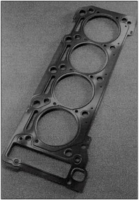
Fig. 7-291. Layered metal head gasket
Function. The sealing function of the layered metal head gasket is essentially dependent on the beads in the spring steel layers. The deformation characteristics permit plastic adaptation to component stiffness, on the one hand, and, on the other hand, great resilience to compensate for dynamic fluctuations in the sealing gap and for thermally induced component deformations. With the use of half-beads in the liquid sealing areas and full beads at the combustion chambers, the compression levels along a given line, required for sealing in each case, are achieved (Fig. 7-292).
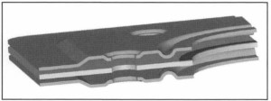
Fig. 7-292. A 3-D section through a layered metal head gasket
The stopper induces an elastic preload in the components around the edge of the combustion chamber. In this way, the fluctuations in the sealing gap resulting from the gas forces are reduced, while at the same time unacceptable deformation of the full beads is prevented. Normal stopper heights lie within a range of from 100 to 150 μm. An intermediate layer may be inserted to achieve the required installation thickness or to accommodate differing thickness adjustments for diesel engines; this intermediate layer has no influence on the sealing function.
At 3 ½ -layer and multilayer gaskets the stopper effect has to be split into the functional layers to protect the full beads. This means, for example, that in 3 ½ _layer gaskets the intermediate layer in the area near the stopper has to be cropped. In this way, the stopper is centered inside the head gasket. Without this distribution of the stopper effect to both functional layers, protection is not ensured for that full bead that does not lie on the stopper side.
Application Examples. Multifunction, Layered Design, Fig. 7-293. Excessive sealing gap fluctuations cause dynamic overloading of the beads; the full beads at the combustion chamber are especially endangered. Relaxation—a reduction in bead force and resilience—occurs and fissures may even appear in the beads. The functional layers in the Metaloflex® head gaskets that are provided with beads use their resilience to compensate for the sealing gap fluctuations occurring in the engine.
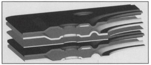
Fig. 7-293. A 3-D view of a head gasket in a multiple functional layer design
With the use of multiple functional layers, the overall amplitude can be distributed to the individual layers and thus reduced to an acceptable level. The total resilience of the gasket rises with the number of functional layers used. In this way, it is possible to ensure function and durability even at low bolt forces and high peak pressures.
Variable Stopper Thickness. Proper stopper design makes it possible to exert a closely defined influence on the sealing gap fluctuation. The gasket is normally between 0.10 and 0.15 mm thicker in the area around the stopper, the exact amount depending on engine stiffness. This causes an increase in pressure and elastic preload in the sealing system.
Where the stiffness in adjacent engine components is not uniform, it may be necessary to graduate the thickness of the stopper. This allows more uniform distribution of pressure on the stopper and thus more uniform preload at the head gasket and engine (or cylinder) block. In this way weak points in components, characterized by low stiffness values, can be preloaded. The available bolt force is directed exactly to the desired areas and thus utilized ideally.
Two embodiments are used in principle: the plastic stopper (Fig. 7-294) and the graduated-height stopper (Fig. 7-295).
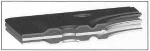
Fig. 7-294. A 3-D view of a head gasket with plastic stopper
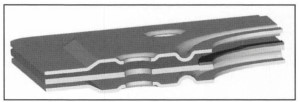
Fig. 7-295. A 3-D view of a head gasket with graduated-height stopper
In the plastic stopper the vertical profile is achieved with a plastic adaptation in the engine, while in the graduated-height stopper the profiling is created during gasket manufacture. Using the graduated-height stopper makes it possible, in contrast to the plastic stopper, to achieve higher profiling even at low installation thicknesses.
Partial Elastomer Coating, Fig. 7-296. With partial coating, only the head gasket surface areas that are relevant to sealing are coated. This makes it possible to omit the coating on the sealing surfaces that extend into the coolant or the motor oil; thus, there is no coating there that could peel off under critical conditions.
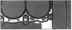
Fig. 7-296. Layered metal head gasket with partial coating
Further advantages of this process are that, with the special application procedure, both the thickness of the coating layer and the coating medium can be selected to suit the application. The coating requirements in the combustion chamber and liquid areas, which differ in part, can thus be properly met. For coolant and oil sealing, a thicker layer and softer elastomer are beneficial if, for example, the mating surface is rough or porous. At the same time, thinner layers are necessary to contain the ignition pressure at the combustion chamber. These conflicting goals can be resolved by selective coating.
Dual Stopper Design for Use with a Cylinder Liner. A modified gasket design is required in many cases where a separate cylinder liner is used. To avoid plastic deformations and to keep the liners from being shifted downward, the necessary sealing and preload forces have to be introduced into the gasket system in a defined manner.
Force application at the liner is closely defined with the use of a so-called double stopper, Fig. 7-297. In this configuration one stopper is formed by a folded bead around the edge of the combustion chamber, while a second stopper is formed behind that bead by overlapping two sheets of metal. The two layers are joined in this overlapping area with a laser welded seam. To achieve ideal response during operations, the stopper force acting on the liner must cause no plastic depression of the liner.
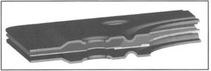
Fig. 7-297. A 3-D view of a head gasket with double stopper
By employing sheet metal of varying thickness, the distribution of the pressure to the two stoppers can be regulated individually. Thus, for example, the stopper at the outside may be thicker by 20 μm; consequently, the larger share of the preload is directed not to the liner but rather to the outside area of the cylinder tube. This stratagem ensures the required preload on the components while at the same time avoiding any displacement of the liner.
Stopperless Design. In gasoline engines, and particularly where aluminum engine blocks are used, it is possible under certain circumstances to do without the stopper.
In this way the elastic deformations of components caused by the head gasket are reduced dramatically. In addition to reducing cylinder deformation, deformations in the area around the valve seats can also be significantly reduced.
The implementation of this concept does, however, require that the bead geometries be matched exactly to the details of the mating components. In gaskets with stoppers, the deformation of the full beads are determined by the thickness of the stopper. Protecting the beads in this way creates ideal conditions with respect to durability and resilience.
Without stoppers, Fig. 7-298, the deformation of the beads depends largely on the stiffness of the components. This means that, depending on the stiffness of the cylinder head and the engine block, the beads are deformed to a greater or lesser extent. Attaining sufficient sealing pressures while achieving ideal durability requires individual adaptation to the conditions prevailing in the engine.
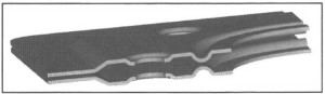
Fig. 7-298. A 3-D view of a head gasket without a stopper
Integrated Supplementary Functions. Integrating a high-sensitivity sensor system directly into the head gasket provides for even more dependable monitoring of processes in the engine: integrated sealing gap sensors, Fig. 7-299.
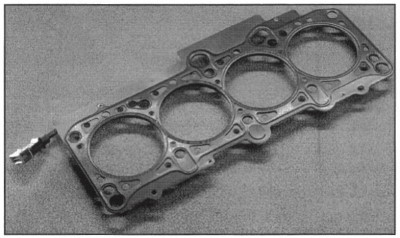
Fig. 7-299. Head gasket with integrated sealing gap sensor
The sensor system uses the enormous pressures created by combustion inside the cylinder. These pressures cause relative movement between the engine block and the cylinder head. The sensor registers this movement and is thus able to detect at an early date irregularities in the engine, such as misfiring or other ignition problems.
The measurement of coolant and component temperatures inside the engine is becoming even more significant since, in conjunction with cooling regulated according to the engine map, for instance, the values registered at the measurement points that were previously used are hardly representative. Particularly in operating ranges where there is little coolant flow or none at all, the temperature of necessity has to be measured at critical points in the engine.
Date added: 2024-07-30; views: 601;