Spectral Data Collection Using LTS. Dual-Channel LTS Systems
A typical sample consists of nanoparticles suspended in a fluid such as pure water. To obtain the properties of the nanoparticles alone, one must measure the transmission properties of the nanoparticles suspended in fluid and the suspension fluid separately. The nanoparticles in suspension are usually contained in a quartz cuvette and referred to as the sample. The suspension fluid is placed in a separate quartz cuvette and is referred to as the reference. The raw transmission spectra for light passing through the sample and the reference are collected and stored separately.
Details of the data acquisition differ depending on how the apparatus is constructed. Here, we describe three implementations of the apparatus used to obtain the raw transmission spectra. In all cases, an important purpose of the optical design is to provide a means for spatially and angularly suppressing both singly and multiply scattered light while optimally coupling zero-angle transmitted light into the detectors. The first steps in data analysis convert the raw spectra into the measured extinction spectrum referred to above. The ultimate goal of inverting the data into a quantitative high-resolution particle size distribution requires accurate, wide-ranging, high-resolution, low-noise extinction spectra.
Dual-Channel LTS Systems. The dual-channel LTS systems described here employ a double-balanced technique, which eliminates both time-varying common-mode light source noise and systematic differences in the two light channels. First, simultaneous acquisition of both sample and reference channels allows one to balance out any temporal fluctuations in the light source. Second, interchanging the sample with the reference and recording a second set of data balances out differences in the two channels. The double-balanced technique can be generally applied to any wavelength or frequency regime with the appropriate choice of source, spectral range, and detectors.
Dual-Channel Wideband Tunable Laser-Based System. The dual-channel laser-based LTS system, Figure 1, was first reported in Li et al. [6] and is briefly described here. This apparatus consists of a computer-controlled tunable laser (TL) and balanced optical system, which provides accurate and precise measurements of sample and reference transmittance over the wide wavelength range of 210-2300 nm. In Figure 1, the light source is a commercially constructed TL, which is comprised of a pulsed Nd:YAG laser with second- and third-harmonic generation using an optical parametric oscillator (OPO) and nonlinear crystals. The laser system outputs beams through three separate ports, which correspond to three wavelength ranges: near-infrared (NIR), visible (VIS), and ultraviolet (UV). The OPO is capable of producing a VIS signal beam from 420 to 709 nm and a NIR idler beam from 710 to 2300 nm. The OPO output is also frequency doubled to produce UV from 210 to 419 nm. The result is a TL light source, which ranges from 210 to 2300 nm with a pulse width of ~5 ns, a pulse rise time of 1 ns, and a repetition rate of 10 pulses s-1.
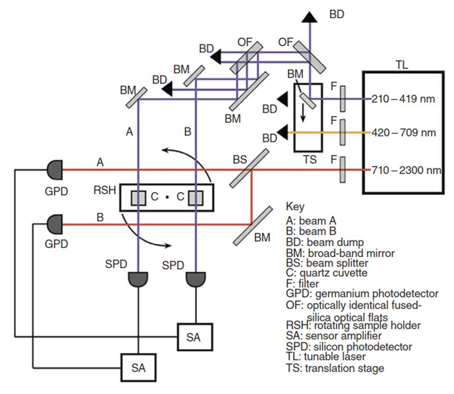
Figure 1. Dual-channel wideband tunable laser system
The laser output power varies substantially over the full wavelength range, generally producing 1-3 mJ of power per pulse in an elliptically shaped output mode with major and minor axes of ~10 mm x 8 mm. Next, the laser beam is well collimated through a series of three 2 mm diameter apertures spaced several centimeters apart. Because of power variations with wavelength, filters (F) are used in front of each laser port to make the output power at the detectors over the entire wavelength range within the same order of magnitude (~1 mJ/pulse), eliminating the possibility of detector saturation.
For the NIR region, the balanced optical system consists of a 50/50 metalized beam splitter (BS), a broadband mirror (BM), and a matched pair of germanium photodiodes (GPD) arranged as shown in Figure 1. Light from two beams (A and B) of nearly equal intensity are directed onto a matched pair of GPD where beam B reflects off of an additional NIR BM. A computer controlled rotating sample holder (RSH) moves sample and reference cuvettes (C) in and out of the selected pair of laser beams during a wavelength scan.
The transmitted and reflected beams of the 50/50 BS are well balanced in the NIR spectral region. However, this type of BS is not suitable for the VIS and UV, so a different scheme is used for these wavelengths. In this case, a BM on a computer controlled translation stage (TS) selectively directs the VIS and UV beams along a single optical path. A matched pair of uncoated fused silica optical flats (OF) followed by a matched pair of BMs are used to split then steer two nearly identical laser beams onto a matched pair of silicon photodiodes (SPD) and sensor amplifiers (SA). Because of time variations in laser power from pulse to pulse, the detector-amplifier modules for a given pair of photodetectors are simultaneously triggered when acquiring data at a selected wavelength.
Extra, unused reflections are captured with beam dumps (BD) to eliminate the possibility of their causing scattered light. Additional baffles not shown are also used to prevent scattered laser light from entering the detectors. The apertures of our detectors are ~2mm in radius and ~80mm from the particle sample. This detection geometry corresponds to a collection solid angle for scattered light of ~1.4 x 10⁻⁴ relative to the straight through transmitted laser beams. A shutter (not shown) is also used to temporarily block the laser beam path prior to each wavelength scan, and the detector amplifiers are triggered to zero their outputs.
The sample and reference cuvettes are each placed in one of the of the two laser beams A and B, and the wavelength of the laser is scanned using 1 nm steps from 210 to 2300 nm at a rate of 5 s/step. The computer controls the RSH and selects which pair of photodiode (GPD or SPD) outputs to record, depending on the wavelength range to be measured. The transmission of both the sample and reference are recorded simultaneously. After the total desired wavelength range is scanned (time duration ~ 10 000 s), the sample cells are interchanged using the RSH, and the process is repeated. The spectral quantities described in Eq. are thus recorded as the raw data at each wavelength in the scan.
Date added: 2025-02-13; views: 496;