Conrod Bolts. Design. Conrod Ratio
The upper and lower halves of the big end are held together with the conrod bolts. These threaded connections must fulfill two functions:
- The conrod bolts must prevent any gap forming in the separation plane between the lower half and the upper half of the big end. The forces that are effective on the conrod bolts include the inertial forces of the conrod and the piston along with a transverse force resulting from off-center loading and the forces resulting from "crushing" the bearing shell protrusion. During engine assembly, the bolts, opposing the effective inertial force, are normally preloaded by controlled tightening to the 0.2 offset limit or rotary torque plus rotation angle.
- The conrod and the cap have to be moved toward one another precisely and secured against shifting (offset). There are several options to choose from:
- a. Guidance by the conrod bolts, the shoulder or grooves of which are in the parting plane and thus prevent the upper and lower halves from shifting.
- b. Guidance by small pins next to the bolts or the bushings that surround the bolts (Fig. 7-31).
- c. Milling toothed ridges into the parting plane.
- d. Guidance by the separation surface at split (cracking) (Fig. 7-32).
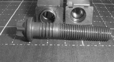
Fig. 7-31. Fitting bearings and expanding bolt
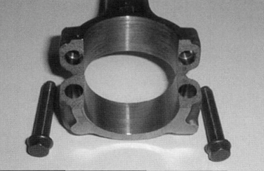
Fig. 7-32. Fracture-split conrod
If pins, bushings, or fracture-split conrods are used, one may do without body-fit bolts. In this case, the structure at the parting surface or the pins and bushings offer sufficient resistance to relative motion between the upper and lower halves.
Design. The following aspects are of significance in regard to conrod design:
- Dimensional stability of the areas that accept the two bearing shells
- Oil channels for lubricating the small end eye may be required (unusual in modern designs)
- Separation of the big end bearing for mounting on the crank shaft journal.
- Fixing and securing the conrod cap.
- Engineering the conrod web to optimize design and/or reduce masses
- Design of critical zones in accordance with loading
Figure 7-33 shows the stress analysis for a conrod with an angular split.
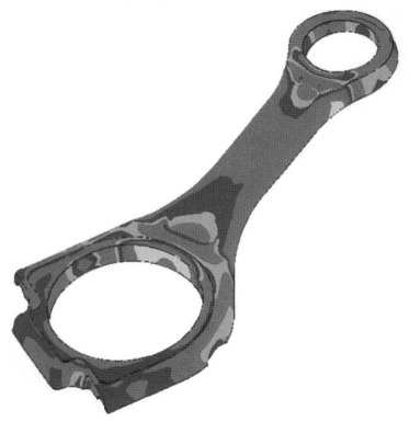
Fig. 7-33. Stress analysis for a conrod with an angular split, with a trapezoidal small end (half model) (Federal Mogul)
To reduce the mass of the piston and/or the conrod, the small end may be flattened toward the top, creating a trapezoidal shape. This shape, for reasons associated with the loading (in turbocharged engines, for example), is advantageous since it permits close spacing to the wristpin bosses and thus reduced wristpin flexure. The big end of the conrod is split to permit assembly on the crankshaft and is held together with two bolts.
The big end is normally split perpendicular to the long axis of the conrod. As an alternative, to reduce the maximum width of the conrod, the big end can also be split at an angle. This angular version makes it possible to pass the conrod (without the cap mounted at the big end) through the cylinder for assembly. The disadvantage of the angled split for the big end is that the blind hole for the conrod bolt terminates in the area subjected to the most severe loading and that great lateral forces have to be handled in the separation plane. Conrods with an angled split are used above all in V-block engines and in large diesel engines, which, because of the loading involved, have large-diameter crankshaft journals.
The big end and small end are joined by the conrod web, which has an I or H cross section. This makes it possible to satisfy requirements for reduced weight at a high section modulus.
Conrod Ratio. The conrod ratio is a comparative geometric magnitude, based on the crank radius r and the distance l between the centers of the small-end and big-end eyes (Fig. 7-29). It is defined as

In passenger car engines, this value is normally between 0.28 and 0.33 with the lower values applicable to diesel engines. The selection of conrod length is influenced by many factors such as the stroke/bore ratio, piston speed, engine speed, peak combustion chamber pressure, engine block height, piston design, etc.
The lateral forces on the piston rise with the conrod ratio. This can, for instance, result in modified specifications for the piston's engineering design. As the conrod ratio falls, the overall height of the engine rises as a result of the increase in cylinder block height. Finally, restrictions imposed by the manufacturing process (cylinder block height) may prohibit a change in the conrod.
Date added: 2022-12-29; views: 1086;