Conrod Manufacture. Manufacturing the Blank. Machining
The blank for the conrod may be manufactured in any of a number of different ways, depending on the particulars of the application:
a. Drop forging. The feedstock material for making up the blank is a steel bar with a round or rectangular cross section, which is heated to a temperature of between 1250 and 1300°C. A roll-forging process is used to effect a preliminary redistribution of the masses toward the big and small ends. As an alternative to roll forging, cross-wedge rolling may also be employed, improving the preliminary geometry for the blank.
The major reforming process takes place in a press or a hammer unit. Excess material flows into flash, which is removed in a subsequent operation. Simultaneous with flash removal, the big eye and, in the case of larger conrods, the small eye are punched.
To achieve the required structural and strength characteristics, the conrod requires various treatment processes, the choice depending on the steel alloy used.
- Hardening with the forging heat (VS)
- Controlled cooling in an air stream (BY)
- Conventional hardening
Then the scale on the blank is removed by blasting; here compression stresses of 200 MPa are generated near the surface. Additional procedures such as fissure inspections follow.
In most cases, the conrod web and the end are cast as a unit and then separated during later machining. Depending on the conrod and the capacity of the available equipment, productivity can be boosted by tandem forging, i.e., shaping two conrods simultaneously.
b. Casting. The starting point for making up the blank is a model made of plastic or metal, comprising two halves that, when put together, create a positive image of the conrod. Several such identical halves are mounted on a model plate and joined with the model for the casting and gating system. In a process that can be reproduced many times, the two model plates are imaged by compacted green sand. The sand molds represent a negative image of the corresponding model plate. Placed one above the other, they form a hollow cavity in the shape of the conrod being manufactured. This is filled with liquid casting iron that is melted in a cupola blast furnace or electric furnace with steel scrap used as the feedstock material. The metal solidifies slowly inside the mold.
c. Sintering. The manufacturing process begins with servohydraulic pressing of the powder, in its final alloy, to create a powder preform. Weighing follows to ensure that this preform is within narrow weight tolerances of ±0.5%.
The sintering process, illustrated in Fig. 7-34, takes place at about 1120°C in an electrically heated, continuous charge furnace. The parts remain here for about 15 min.

Fig. 7-34. Process-sinter-forged conrod
Subsequent forging merely reduces the height of the component in order to increase component density to the maximum theoretical limit. Then ball blasting is used to relieve the strain in the surface to the desired level.
Since the forging procedure in this manufacturing process is costly, developments are currently being pursued with the goal of eliminating this by using new powder technologies.
Machining. The blanks are machined down to the final dimensions. In mass production this is done in fully automatic lines that are integrated into the engine manufacturing process. Machining centers with a lower degree of automation are available for smaller production runs. After machining, the finished part is weighed and classified. Conrods in a particular weight class are then installed in any given engine. If the blank was already manufactured to close weight tolerances, then it may be possible to do without this classification step.
In order to achieve the specified weight for the finished conrod, tabs can be provided at the small and/or big end of the blank (Fig. 7-35). During mechanical finishing, these tabs are ground down far enough that the specified weight value is attained.
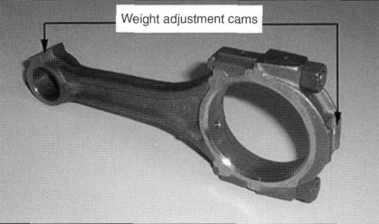
Fig. 7-35. Traditional conrod; body and big end cap forged separately and secured with nuts and bolts
In more modern manufacturing processes, the manufacturing parameters can be monitored exactly so that blanks can be made within adequate weight tolerances.
Thus, grinding to remove excess material provided deliberately for this purpose is seen only rarely today. The processing steps are described below, by example, for conrods that are split after manufacture (cracking):
- Grinding the faces of the big and small ends
- Prespindling the big and small ends
- Drilling and tapping the bolt holes
- Cracking
- Bolting the cap to the upper half of the big end and— if necessary—inserting the guide bushing
- Finishing final grinding
- Drilling out the small eye
- Spindling the big end and optional honing
The term "cracking" of "fracture splitting" describes the separation of the conrod web and the cap by breaking the latter away during processing. The prerequisites for this process are, in terms of the materials, a coarse-grain structure and, in terms of equipment, a cracking unit that can apply the required breaking energy at high speed. If the material exhibits a ratio of tensile strength to tensile yield strength (0.2 offset limit) that is near 2:1, then cracking can be carried out without any major deformation of the part. Blanks made with any of the modern manufacturing processes can be split by cracking. The difference in the design of the conrod is shown in Fig. 7-36.
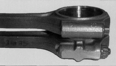
Fig. 7-36. Design differences between a fracture-split conrod (above) and a sawed conrod
In preparation for cracking, notches are made in the side surfaces of the big-end eye by laser or broaching to achieve a deep notch effect at the desired separation plane (see Fig. 7-37). The large eye is positioned over a two-part breaker drift and fixed in place. The breaker drift is spread at high speed, and the stresses created in the workpiece initiate breaks within the notches. These breaks then propagate radially outward. If this process runs optimally to conclusion, then the out-of-roundness following cracking will be 30 µm at the most.
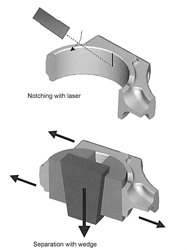
Fig. 7-37. Conrod fracture splitting
The advantage offered by fracture splitting is found above all in reducing the number of processing steps. Machining the separation surfaces, which used to be standard, can be done away with. The two halves fit together exactly after cracking and, with the irregular surface, are secured against relative movement, eliminating the need for any additional guide elements. A further benefit is found in the use of a simplified conrod bolt since it does not need to carry out guidance or lateral fixing functions. Fracture-split conrods are an economical alternative to conrods separated in a conventional fashion.
Date added: 2022-12-29; views: 1220;