Oil Control Rings. Ring Combinations
Oil control rings are of particular significance in managing the engine's oil supply and consumption; they are subdivided into the following:
- Self-expanding cast iron rings (e.g., to support oil control action in high-speed engines and as the only oil control ring on a piston)
- Spring-expanded and spring-backed oil control rings, manufactured as castings, for gasoline and diesel engines
- Spring-expanded, oil control rings made of profiled steel, for gasoline and diesel engines
- Spring-expanded, oil control rings made of steel strip, for gasoline engines.
The fundamental versions of oil control rings are the following:
- The shoulder ring (Fig. 7-42a) and shoulder/bevel ring (Fig. 7-42b) are, for all intents and purposes, compression rings with oil control properties.
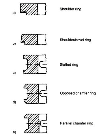
Fig. 7-42. Oil control ring (self-expanding cast rings)
The slotted ring (Fig. 7-42c) has an oil control effect because of the high surface pressure at the edges of the two rails. The slots at the circumference facilitate the return flow of the oil stripped off the cylinder wall.
Opposed chamfer (Fig. 7-42d) and parallel chamfer (Fig. 7-42e): Chamfering the contact surfaces of the slotted ring additionally increases the contact pressure at the edges, in turn enhancing stripping action.
Spring-expanded and spring-supported oil control rings (Fig. 7-43) are high-flexibility sealing rings with improved capacity for filling available space in the groove. They can adapt to compensate for cylinder warping and ensure particularly low oil consumption in the engine.
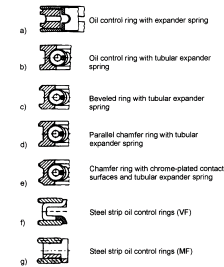
Fig. 7-43. Spring-expanded and spring-supported oil control rings
Oil control ring with expander spring (Fig. 7-43a): This version is found primarily in piston ring sets used for repairs.
Oil control ring with tubular expander spring (Figs. 7-43b–e): In this ring, the surface pressure and shape compensation capability are reinforced with a coiled, cylindrical compression spring (tubular spring).
Strip steel oil control rings (Figs. 7-43f and g) are used primarily in gasoline engines for passenger vehicles. They comprise two steel rails and a steel spacer spring.
Ring Combinations. The combination of rings for gasoline engines shown in Fig. 7-44 illustrates an example of current trends in the selection of rings.
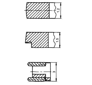
Fig. 7-44. Ring combinations for gasoline engines
1st groove: Steel ring 1.2 mm high, with crowned running surface, nitrided on all sides.
2nd groove: Shoulder/bevel ring 1.5 mm high, made of standard gray cast iron.
3rd groove: Strip steel oil control ring, 3.0 mm high, with chrome-plated steel rails at the contact surface or with nitride spacer springs and steel rails nitrided on all sides.
A typical combination for passenger-car diesel engines is shown in Fig. 7-45.
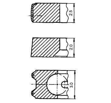
Fig. 7-45. Ring combinations for diesel engines
1st groove: Chrome-ceramic coated, rectangular ring, 2.5 mm high, spheroid casting, asymmetrically crowned contact surface, sharp lower running edge.
2nd groove: Negative-twist beveled ring, 2.0 mm high, made of gray cast iron, hardened.
3rd groove: Chrome-plated oil control ring with tubular spring, 3.0 mm high, made of standard gray cast iron, with running edge ground to form a profile, centerless grind at the butt joint for the tightly wound tubular spring.
At higher thermal loading, the first ring is a double trapezoid ring, 3.0 mm high, which otherwise exhibits identical characteristics.
Date added: 2022-12-29; views: 2312;