Rocket Propulsion, Solid Propellant
Solid propellants typically consist of a mixture of fuel and oxidizer, whereas liquid-propellant components are generally stored in separate tanks and combined in a combustion chamber. Although solid and liquid rocket propellants are usually employed separately, they are used together in the hybrid rocket, the most common combination being solid fuel and liquid oxidizer. The propellants used in the cold-gas thrusters employed to position some spacecraft in orbit are unusual in that they are generally stored as a gas.
The rocket in its simplest form is believed to have been invented by the Chinese in the eleventh century AD using a solid propellant similar to what was later called gunpowder. The Englishman William Congreve initiated modern rocketry research and development in the early nineteenth century when he built the first gunpowder rocket weapon systems to challenge Napoleon’s invasion plans for England.
Solid rockets continued to be developed throughout the nineteenth century and were used during World War I, but their power and efficiency (now measured by the quantity ‘‘specific impulse’’) were limited by the available propellants. Thus it was that Russian rocket pioneer Konstantin Tsiolkovsky suggested the use of liquid propellants in 1903, and American researcher Robert Goddard began their development in the early 1920s.
Goddard had conducted tests with solid fuels to refine his technique, and in 1915 he found that a tapered nozzle increased the expulsion efficiency of the exhaust gases by some 64 percent. He subsequently used the nozzle in all his rocket work, and it was adopted by others. Since the 1920s, the majority of rocket systems required to carry significant payloads, especially into space, have been based on liquid propellants. Despite this, solids have their uses.
By the end of the twentieth century, solid- propellant rockets were available in all shapes and sizes and were often chosen over liquid systems because they are simpler and can be stored longterm without maintenance. They are widely used, for example, by the military services to power missiles, torpedoes, and aircraft ejection seats.
On a larger scale, their inherent storability has made them ideal for intercontinental ballistic missiles (ICBMs), which may be required at very short notice. Solid-propellant rockets are also used in the space industry as launch vehicle stages, strap-on boosters and stage separation devices, and sometimes as ‘‘upper stages,’’ which boost spacecraft to their final orbit or toward the planets.
There are two main types of solid propellant: homogeneous or double-base propellants, which are limited in power (e.g., nitrocellulose plasticized with nitroglycerin plus stabilizing products); and the heterogeneous or composite type. Composite propellants consist of a mixture of fuel and oxidizer, the latter providing the oxygen for combustion. An oxidizer in common use is crystalline ammonium perchlorate (NH4ClO4 or AP). It is mixed with an organic fuel, such as polyurethane or polybutadiene, which also binds the two components together.
The inclusion of a plastic binder produces a rubbery material, making the propellant relatively easy to handle. Performance is enhanced by adding finely ground (10 micrometers) metal particles of aluminum, for example, which increase the heat of the reaction due to the formation of metal oxides. As an example, the propellant used in the Space Shuttle solid rocket boosters is comprised of 14 percent polybutadiene acrylic acid acrylonitrile (binder and fuel), 16 percent aluminum powder (fuel), 69.93 percent ammonium perchlorate (oxidizer), and 0.07 percent iron oxide powder (catalyst).
A propulsive device that uses solid propellants to move a vehicle is known as a rocket motor or solid rocket motor (SRM). Although the terms motor and engine are interchangeable in colloquial English, it is customary to call propulsive devices using a solid propellant motors, and those using a liquid propellant engines.
A typical SRM comprises only a few major components: a motor case that contains the propellant grain (or charge), a surrounding insulating blanket or propellant liner, an ignition system, and an exhaust nozzle (Figure 30). The motor case is typically made from a carbon composite or Kevlar composite by a process known as filament winding, which produces a strong yet lightweight structure. The propellant liner acts as both a thermal insulation blanket and a flame inhibitor and supports the propellant grain during manufacture, as it is poured into the open- ended motor case.
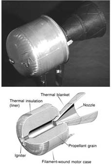
Figure 30. A solid rocket motor used as a satellite apogee kick motor; the diagram shows the major components
A typical ignition system operates as follows: a power supply sends a current pulse to a pyrotechnic cartridge, which ignites a small sample of the propellant in a steel or glass-fiber housing. This produces a controlled amount of hot gas that ignites the main motor, much like a detonator in an explosive device.
The typical exhaust nozzle, or expansion nozzle, consists of two sections: one convergent, the other divergent. The narrowest part of the nozzle, called the throat, is designed to maintain the required pressure within the motor case and regulate the outflow of combustion gases; it is also the region of transition from subsonic to supersonic flow. The exhaust gases expand and accelerate rapidly as they leave the motor, and it is the exit cone that controls the expansion of the exhaust plume.
In operation, the SRM has no need of the complex piping, pumps, and pressurization systems of the liquid rocket engine. The SRM must, however, be designed to give precisely the required amount of thrust and total impulse since it cannot be throttled, easily stopped, or restarted. Where two SRMs are used together, as on the solid rocket boosters of the Space Shuttle, they must also be precisely matched to provide the same thrust profile and to ensure that they cease firing together.
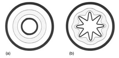
Since the thrust available from a block of propellant is proportional to the area of the combustion surface, the only way to control the magnitude of the thrust is to offer varying surface areas for combustion throughout the burn. The active area can be increased by making a cylindrical hole through the center of the block so that the hole enlarges radially and the thrust increases as the propellant burns. Constant thrust, which is more often required, can be provided by a starshaped bore (Figure 31). A variation in thrust throughout the burn can be arranged by varying the cross-section along the length of the propellant grain.
Although the performance of solid propellants, in terms of thrust derived per unit mass, is generally inferior to that of liquid propellants, solids continue to be used in many applications. This is mainly because they are easier to handle and store and are simpler, therefore more reliable, in their mode of operation.
Date added: 2023-11-02; views: 797;