Radio Receivers, Coherers and Magnetic Methods
From 1900 to about 1914, when Morse code was the normal language of radio communication, a variety of methods for the detection of electromagnetic radiation were employed. Two of the more successful utilized discoveries made during the nineteenth century, namely (1) the property possessed by some types of loose contacts to cohere when activated by radio-frequency currents and go from a non-conducting to a conducting state and (2) the phenomenon of hysteresis in the magnetization and demagnetization of magnetic materials.
Detectors based on these properties were in common use until their gradual replacement by crystal diodes and by vacuum tubes (or valves), which were becoming common components of electromagnetic wave detector circuits just before World War I.
Coherers and magnet materials were not in themselves detectors, but they acted in conjunction with other circuit elements to render radio waves sensible to human beings by producing visible or audible signals. While coherers could be made to operate galvanometers, printers, and earphones, the output of magnetic detectors was sufficient only to operate earphones.
In 1890 the French experimenter Edouard Branley was the first to note that metallic powders, iron filings for example, exhibited the property of coherence. Subsequently, several workers investigated the phenomenon and produced their own devices, examples of which are shown in Figure 6.
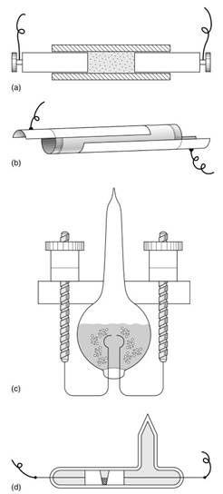
Figure 6. Types of filings coherers: (a) Branley, 1890; (b) Popov, 1895; (c) Lodge, 1895; and (d) Marconi, 1895
Some of the more significant contributions to the development of coherers were made by Oliver Lodge in Britain and by Alexander Popov in Russia, and both men devised their own circuits to be used in conjunction with their detectors. There was no standard form of coherer, nor did there appear to be particular suppliers of the devices.
Many types were developed, in fact almost as many as there were experimenters, and they ranged in structure from solid materials in contact to powders. They were often precisely engineered, although it is not clear that precision was really required. Experimenters had to take into account the fact that once the coherer was put into the conducting state it did not return to its starting condition of nonconduction.
In many devices the original condition could be obtained only by mechanical interference, shaking or striking the coherer for example. Some elaborate arrangements were used to achieve correct and reliable operation and to overcome the disadvantage of slow operating speeds that were contingent upon a mechanically operated device. If wireless telegraphy were to be a serious competitor to the existing terrestrial and submarine telegraph cables, then high signaling speeds would be essential.
Terrestrial telegraphy could operate at hundreds of words per minute, and even very long submarine cables could carry messages at scores of words per minute. Mechanically operated coherers found it difficult to achieve speeds greater than 10 to 20 words per minute, which did not present serious competition to existing means of telegraphy.
There were some materials that displayed the properties of coherence and returned without external action to the nonconducting condition. Substances used in such self-restoring or autocoherers were most commonly steel, carbon, and mercury in various combinations (Figure 7).
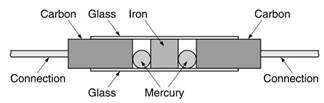
Figure 7. Auto-coherer
Other such devices were constructed by instrument makers such as E. Ducretet of Paris. In spite of great interest in coherers and their common use as radio detectors, no satisfactory theory of their operation has been given.
There were several methods of using coherers, and a typical circuit is shown in Figure 8. The battery served two purposes: to provide current through the galvanometer and earphone and to keep the coherer in a high-resistance, or sensitive, condition.

Figure 8. Basic coherer circuit
In this state very little current flowed around the circuit abcd. However, when a radiofrequency signal was present in the aerial circuit, the resistance of the coherer dropped significantly, resulting in a sudden increase in the current, which caused the galvanometer to deflect or to be heard as a click in the earphone.
Magnetic detectors, a second type of early detectors, fell into two broad groups: (1) electrodynamic detectors, in which the presence of a radio signal was shown by the movement of a needle or a mirror, or (2) magnetic hysteresis detectors, in which the oscillatory field changed the state of magnetization of a piece of ferromagnetic material due to an aerial current. A common form of the magnetic hysteresis detector was that developed by Guglielmo Marconi (Figure 9).

Figure 9. Schematic drawing of Marconi’s hysteresis detector
A loop of iron wire driven by a clockwork motor passed under two magnets and was cycled around a hysteresis loop (see Figure 10). Any oscillating decreasing currents in the aerial coil would tend to move the iron to a magnetization state corresponding to the path 1 to 0, and the change would be heard as a signal in the earphone via the shorter secondary coil surrounding the wire.
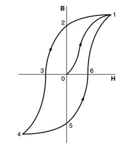
Figure 10. Hysteresis loop
Before World War I, radio communication had largely been restricted to ship-to-shore communication and to military uses, and coherers and magnetic detectors were adequate for these applications. Although widely used for the reception of Morse signals, these devices were unsuitable for the detection of continuous waves. In the first decade of the twentieth century, continuous waves had been generated, typically by high-speed alternators.
Although speech had been broadcast, these experiments had been desultory. During World War I, much attention was devoted to developing wireless telephony, and vacuum tubes were found to be the most effective way of generating continuous radio waves that could carry speech. After the war, particularly when the market for radio widened in the 1920s to become a fully commercial consumer- oriented industry, coherers and magnetic detectors vanished to be replaced by vacuum tubes and the crystal detector.
Date added: 2024-03-05; views: 796;