Radio Transmitters, Continuous Wave
In the 1900s, most contemporary wireless telegraphy transmitters were spark-gap generators. Because of their high radiation resistance, the waveforms produced by a spark gap died out, or damped, quickly. While damped waveforms were not a problem for telegraphy, they presented a serious obstacle for telephony because continuous voice signals needed to ride on continuous waves. Continuous wave transmitters had to be developed for wireless telephony.
The arc generator was an early step in the development of continuous wave transmitters. The arc phenomenon appeared when two conductors previously joined were separated; the current kept flowing between the separated conductors, and a flame-like arc was established. In the 1890s in Britain, Hertha and William Ayrton discovered that an electric arc had a negative resistance. Connecting an arc to an ordinary oscillation circuit, the arc’s negative resistance compensated for the positive radiation resistance and thus reduced the damping effect.
The electric arc could therefore be used to construct a continuous wave oscillator. William Duddle, Ayrton’s student, implemented this idea with his ‘‘singing arc’’ circuit, in which an arc lamp was connected with a capacitor and an inductor in parallel (Figure 20). This circuit could generate continuous waves up to 15 kilohertz. In 1903, the Danish physicist Valdemar Poulsen transformed the Duddle arc into a megahertz oscillator by replacing air with hydrogen gas, applying a magnetic field, using a water-cooled positive copper electrode, and rotating the carbon electrode.
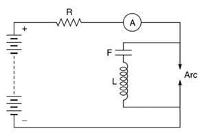
Figure 20. Duddle’s singing arc circuit
In the 1910s, the Poulsen arc became an important technology for wireless telegraphy, but it was not a genuine continuous wave transmitter. British engineer John Ambrose Fleming demonstrated that an arc generator produced a series of short pulses instead of continuous waveforms.
A promising candidate for a true continuous wave radio transmitter was the high-frequency alternator. The alternator, a technology for producing alternate electricity, used the principle of electromagnetic induction. By rotating an armature wound with coils in a fixed magnetic field, an electromotive force was induced in the coils. An alternator was typically used to generate highpower electricity below 150 hertz.
In 1901, Reginald Fessenden proposed to generate radiofrequency waveforms with a high-speed alternator and to couple these waveforms directly to the antenna circuit. Unlike the spark-gap transmitter that produced damped waves, the alternator-based transmitter would provide fully undamped waves as long as its armature’s motion was maintained. To design this kind of alternator, Fessenden contracted with the General Electric Company.
The most critical technical challenge for its development was speed. A radio alternator required the armature to rotate at 50,000 cycles per second or more so that the signal frequency could exceed 50 kilohertz. At the time, no known mechanical armature could withstand the centrifugal force produced by such a high rotational velocity, but General Electric engineer Ernst Alexanderson was eventually able to overcome this problem. In his design, the rotary armature was replaced by two stationary armatures and a rotary steel disk, the circumference of which was embedded with iron teeth, or poles of an electromagnet.
An electromotive force could be induced in the coils, and one could increase the frequency of the electromotive force by adding more poles on the disks’ circumferences. Rapid disk rotation did not pose the mechanical problem of a rotating armature.
A schematic drawing of Alexanderson’s alternator is shown in Figure 21. A magnetic flux, M, that is produced by a field coil, S, passes through the iron cores E1 and E2 of the armature coils S1 and S2. The rotary iron disk, J, has teeth, Z, on its periphery that can extend to the space between the two iron cores E1 and E2. When a tooth of the iron disk is in the gap between the iron cores, the overall reluctance of the magnetic circuit is small, so the magnetic flux, M, is large and the induced voltages on S1 and S2 are large.

Figure 21. The Alexanderson alternator
When there is no iron tooth between the cores, the air gap contributes a large reluctance to the magnetic circuit, so the magnetic flux, M, is small and the induced voltages on S1 and S2 are small. Therefore, as the disk rotates, the induced voltages vary periodically between a maximum value and a minimum, and the frequency of this variation is the number of teeth multiplied by the angular velocity of the disk.
Based on Alexanderson’s design, General Electric successfully made a 2-kilowatt 100- kilohertz alternator in 1909 and delivered it to Fessenden. Following the 1909 machine, alternators with higher power and frequency were further developed. Although gradually replaced by tube transmitters, alternators had greater survivability in long-distance communications. The U.S. Navy’s alternator in Hawaii remained operational until 1957. Another alternator in Massachusetts was used by the U.S. Air Force until 1961.
Another continuous-wave transmitter technology used vacuum tubes. Invented by Fleming and American Lee de Forest in the mid-1900s, vacuum tubes were first used in radio detection. Their potential in radio transmission was not explored until the early 1910s. By about 1912, de Forest, Fritz Lowenstein, and Edwin Armstrong in the U.S, H.J. Round in Britain, and Alexander Meissner in Germany had all conceived the idea of vacuum-tube oscillators.
They discovered that when connecting the output of a tube amplifier with its input via a resistive-inductive-capacitive network an oscillatory electric current would appear at the circuit. The reason, de Forest argued, was that the amplifier and the feedback network made the entire circuit a regenerative system. Signals from the tube’s output were directed to its input and were further enhanced by amplification.
Because the feedback network directed only a narrow frequency band to the input, the selfregenerative wave was nearly sinusoidal. The explanation implied that the square of the resonating frequency of a tube oscillator was inversely proportional to the inductance and capacitance of the overall circuit. Therefore, by adjusting the inductors and capacitors in the feedback circuit, one could vary the resonating frequency of a vacuum-tube oscillator.
A diagram of a primitive vacuum-tube oscillator, proposed by Meissner in 1913, is shown in Figure 22. When a tiny resonance is produced at the circuit of L1, L2, and C, it is coupled to the vacuum tube’s grid, G, through the inductor L3. The resonating signal is then amplified at the tube’s plate, P. The amplified plate current is coupled to L1 through the inductor, L4, and hence enhances the original resonance. Such a feedback cycle goes on and on until the resonating signal gains its maximum.
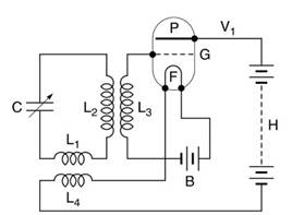
Figure 22. Meissner’s oscillating circuit
The vacuum-tube oscillator became the dominant radio transmitter after 1912. But when engineers began to explore waves beyond 10 megahertz during World War I, the de Forest-type vacuum tube oscillator was found to be inadequate because it was necessary to either shrink the tube’s size or change the circuit structure in order to obtain high frequencies.
In 1920, H. Barkhausen and K. Kurtz in Germany proposed raising the oscillator’s frequency to 1500 megahertz by giving a strong positive bias to the tube’s grid. The Barkhausen-Kurtz oscillator was the most popular ultrashortwave transmitter until the invention of microwave devices in the 1930s.
Date added: 2024-03-05; views: 846;