Computed Tomography (CT). Magnetic Resonance Imaging
Since the invention of computed tomography (Hounsfield 1974), the examination technique for the facial skeleton and particularly the TMJ has entered a new phase. Ever more refined improvements of the X-ray tube placement and of the detector system have made it possible to reduce the initial exposure time of 5 minutes down to a few seconds, and this has made possible major advances.
Modern equipment today consists of approximately 1000 detectors that can be tipped and are mounted in a fixed ring arrangement and an independently moved, fan-shaped single X-ray beam. Fourth generation CT is a robust instrument that permits localization of large lesions of the dental area and, on the basis of the measured density, even permits specific diagnosis. Using 2000 registered gray values that would be impossible to discern with the naked eye, specifically oriented sections (“windows”) can be selected to portray in the final picture the gray scale of bony or soft tissue structures. Positioning of the patient for examination of the TMJ, however, is associated with difficulties due to the construction characteristics of the instrument.
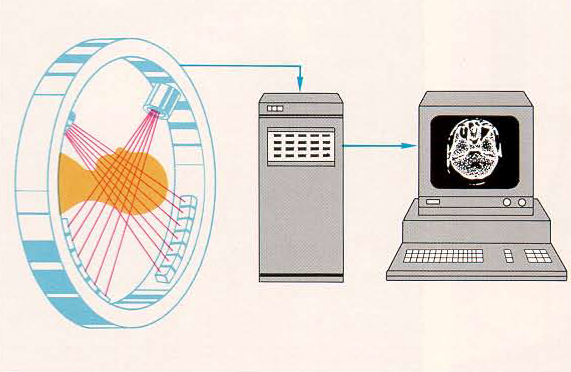
Diagram of the function of a CT. The X-ray tube and the detector system are mounted in a frame that can be rotated and tipped. While the “frame" rotates around the axis of the patient, the fan-shaped X-ray beam scans an axial section of 212 mm thickness, and the detectors measure the radiation intensity behind the object. The volume elements of the selected layer are then computed and the picture is synthesized on the monitor.
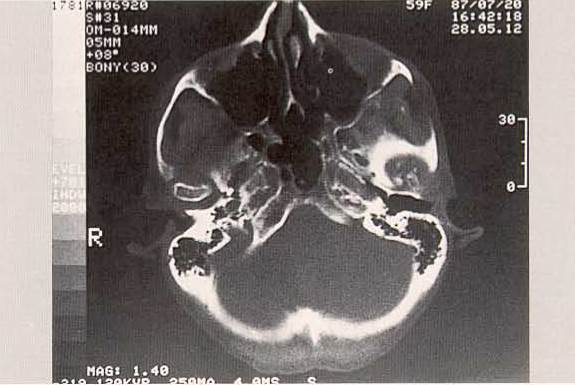
338. Example of an axial depiction of the TMJs in the condylar plane. This pictorial overview reveals an intact right condyle; the remnant of the left condyle is evidence of the postoperative condition. Note the expansive arthrosis at the joint fossa.
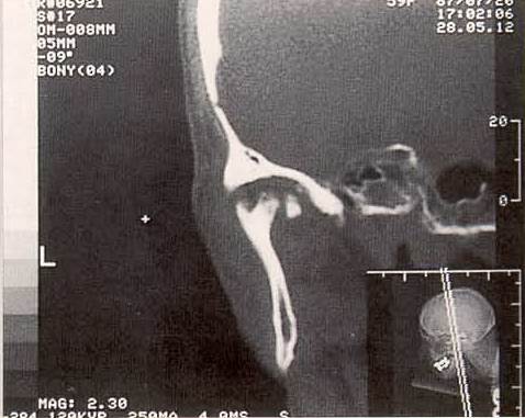
Example of coronal direct scanning of the TMJs. Enlarged representation of the patient shown in Figure 338, with reclined skull. Note the skull positioning of the patient, who reclines face down for this CT (lower right insert).
Using numerous axial plane scannings, it is possible to reconstruct sections in the paramedian plane, e.g., for lateral depiction of the TMJ. Because the image formation of such reconstructed images is less than in direct projections, resolution of the final image is also not of the same quality. Improvement of the situation can only be achieved if the number of points in the photographic matrix is increased by means of direct projection.
For this reason, whenever possible the patient should be placed in the gantry in a very special position: The paramedian plane of the TMJ is positioned in the tipped gantry in such a way that the plane is positioned like an axial projection. The result is a lateral and sharply depicted scan that can display the disc in at least two dimensions if the soft tissue window is selected. This represents great progress. In order to position the patient in this special way, various positioning aids are described in the literature; however, in reality such aids are usually impossible to use if the examination requires an extended period of time or if the patient is elderly.
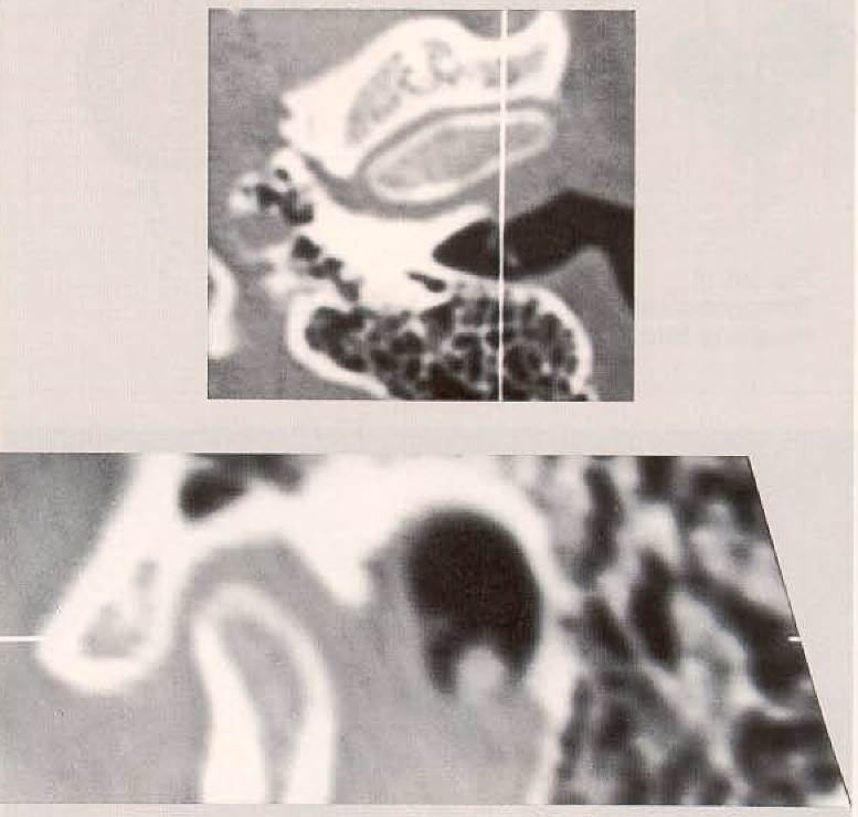
Lateral reconstruction from axial CT layers represented with the bone window. This figure depicts a “zoomed" section from an axial layer al the height of the condyles. The white vertical line that traverses the mastoid cells, the lateral condyle region and the lateral portion of the articular eminence describes the plane of section for the computed lateral view of the TMJ (below).
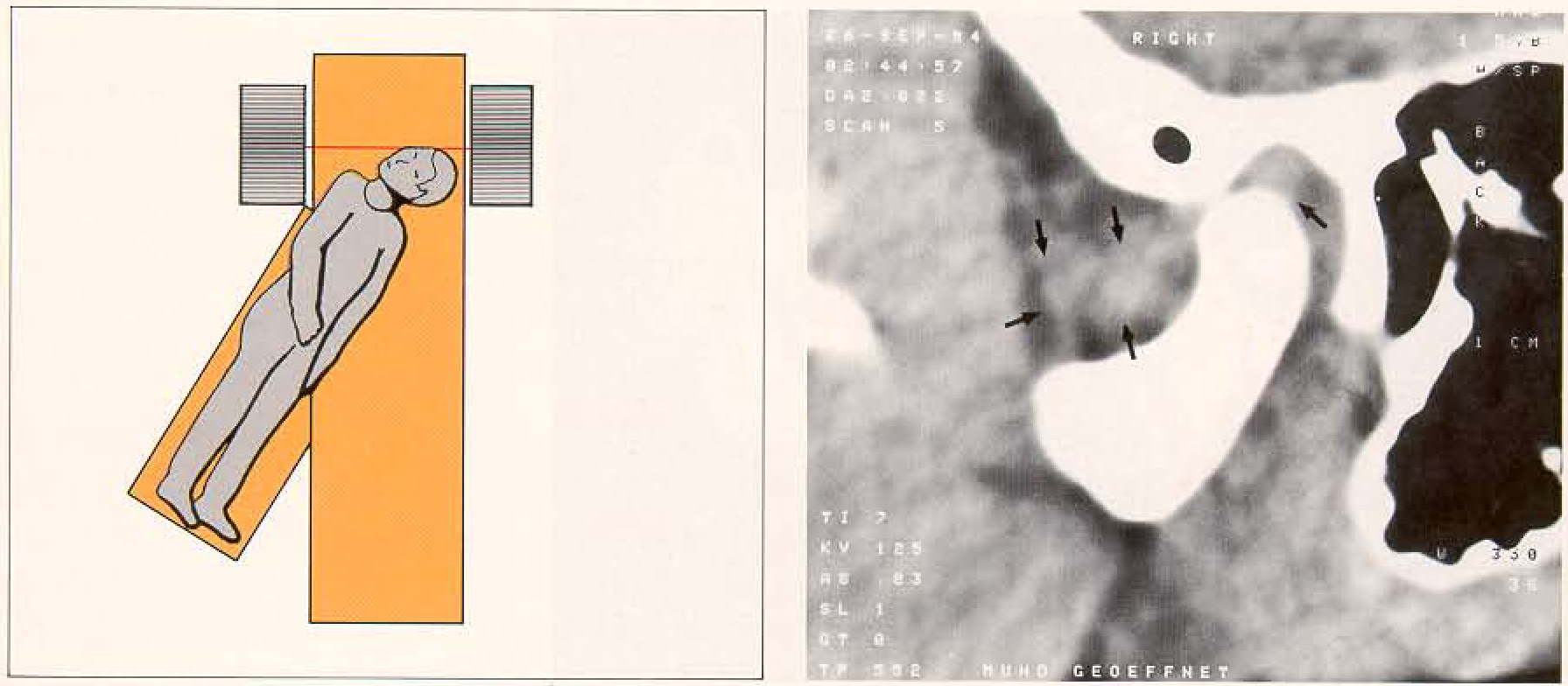
Direct lateral representation of the right TMJ using the soft tissue window. With the patient's jaw in rest position, the perforated and anteriorally displaced disc is visible (arrows). To produce this type of direct depiction, the patient must be placed in the gantry in such a way that the paramedian TMJ plane is positioned as for an axial projection. The diagram (left) shows how the patient is positioned in thegantryof the CT apparatus to get a lateral section through the TMJ region, as in an “axial” direct view. This positioning of the patient demands an additional lateral table, as shown. This position requires great flexibility of the patient's cervical vertebrae.
Magnetic Resonance Imaging. Magnetic resonance imaging, also known as magnetic resonance tomography, is an image-producing technique without the use of ionizing radiation. The creation of such an image involves the use of atoms, e.g., hydrogen atoms, which possess a nucleus with a magnetic moment and a nuclear rotatory impulse. Hydrogen is present in sufficient quantities throughout nearly all body tissue and its nuclear constituents (the protons) possess the characteristics of gyroscopes and magnets.
The application of an external magnetic field causes the magnetic moment of the nucleus to align parallel to the field lines (see Fig. 342).
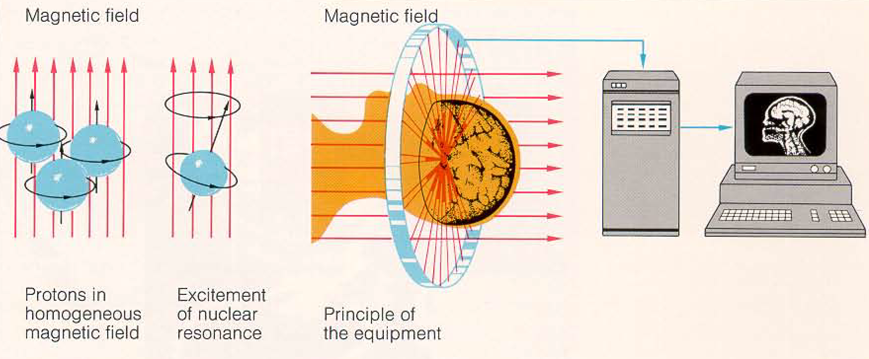
Functional diagram for magnetic resonance imaging
An electromagnetic pulse in resonance frequency applied perpendicular to these lines of field, tips the magnetic moments away from their primary direction and forces them to elicit a signal that can be processed into an image with the help of a computer. The image will have signal-rich (light) and signal-poor (dark) zones. A qualitatively satisfactory TMJ image requires the use of special surface coils.
Date added: 2022-12-17; views: 812;