The Angular Zbuffer Algorithm (AZB)
The AZB algorithm deserves special attention because it possesses features markedly different compared with the techniques presented in the previous section. The main advantage of this algorithm is that, not only can it be used to solve the RSQ problem (second subproblem of the RTT), but also it is especially applicable to the SIP strategy to solve the FPS (first subproblem) of the RTT.
The AZB algorithm is based on the light buffer technique used in computer graphic design for solving problems of hidden lines or surfaces to determine which areas of a given environment are visible from a point in space (the source).
The algorithm is based on the division of the space observed from the source point or from the facets in spherical sectors. These spherical sectors are called anxels, and they are defined by the spherical coordinates 0 and ф with respect to the coordinate system defined by the source or by the facets (see Fig. 11). The number of anxels depends of the angular increments Δθ and Δф) that define the size of the anxel:
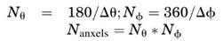
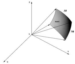
Figure 11. Anxel definition as a function of the angular steps Δθ and Δф
The coordinates θ and ф define a plane called the AZB plane that contains the objects located in each anxel, and it identifies the directions where the object is located, taking the source point or each facet as reference. The AZB plane of a point (like the source) is easier to obtain than the AZB plane of a facet.
The 2-D scene with planar facets depicted in Fig. 12 illustrates AZB of the source point. S marks the position of the source. Ifthe space is divided into eight angular regions, each region will contain the facets given in Table 1 that contain the information of the so-called AZB matrix associated with the source point. For example, in anxel 2 (angular margin from 0° to 45°), there are only two facets.
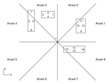
Figure 12. Example of 2-D scenario and additional division in angular sectors
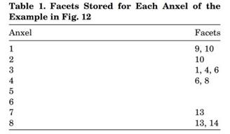
Then, to determine whether a direct ray reaches an observation point placed in anxel 1, the RSQ must only be performed for the two facets contained in that anxel, instead of for the 16 facets that appear in the scene. The facets that do not satisfy the criterion of the back face culling (5) cannot hide a ray traced from the source to a given observer, and they are not stored in the AZB matrix. For this reason, facets 11 and 12 have not been considered in the table for anxel 1.
This idea can be generalized easily to a three-dimensional (3-D) case. If a model composed of planar facets is considered, the spherical coordinates of the facet vertices are calculated, which define a window based on the minimum and maximum θ and ф coordinates (θmin, θmax, fmin, fmax) used to determine the anxel where the facet must be stored. If the scene contains curved surfaces, then the computation of this window becomes more complex.
A this problem consists of enclosing the surface within a boundingbox. Once the surface is enclosed, the eight vertices of the box can be considered for the creation of the AZB matrix by considering the spherical coordinates of the eight vertices as a whole, in a similar way to the vertices of a facet for the case of planar surfaces (see Fig. 13).
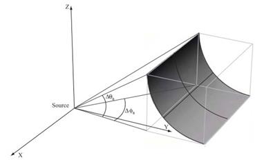
Figure 13. Angular margins of a surface considering the enclosing box
All information that corresponds to the planar and the curved surfaces is stored in the AZB matrix, which can be considered as a grid in the coordinates 0 and ф, as depicted in Fig. 14. Each vertex of an entity is placed in an element of the grid, and the entity will be contained in the set of elements of the grid defined by its vertices.
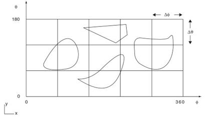
Figure 14. Example of the storage of different surfaces in a grid defined by the AZB matrix
The application of the aforementioned algorithm is only valid for the analysis of direct ray shadowing because the source has been taken as a reference. Some modifications must be performed to apply this algorithm to reflected and diffracted rays.
In reflection, the application of the algorithm is very easy for the planar entities of the scenario, and subsequently image method for reflection can be applied. Therefore, an AZB matrix can be built for every image in a given scenario. The only difference is that the space to be divided in this case, is only the region where the reflected ray can appear. The so-called reflection window defines this region (see Fig. 15).
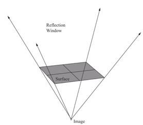
Figure 15. Reflection window for a planar surface
The definition of the reflection window is more complicated for a curved surface. In this case, all possible directions of reflection have to be considered with respect to all points on the surface. To avoid this, an AZB matrix is created for each of the eight vertices that define the box that encloses the surface. The angular margin for the total reflection window is obtained as the union of the regions defined by each of the vertices of the box (see Fig. 16). More details about the complete procedure to create this window can be found in Reference 24.
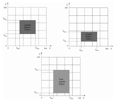
Figure 16. Generation of the total angular margin of a surface from the angular margin of two points. The procedure can be generalized to the eight vertices of the enclosing parallelepiped
must be created from the properties of this effect. When a ray arrives at an edge, infinite rays are diffracted, forming a cone whose vertex is the diffraction point, the axis is the edge itself, and the angle is the same as that formed between the edge and the incident ray. This cone is called ‘‘Keller’s cone’’. The region contained within this cone defines the diffraction window.
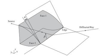
Figure 17. Coordinates α and β that define the AZB window for diffraction
New angular coordinates must be considered to limit this diffraction window according to these properties. This coordinates are α and ß, defined in Fig. 17. Therefore, analogous to the reflection case, there is a diffracted window for every illuminated edge that corresponds to an AZB diffraction matrix.
Date added: 2024-03-07; views: 734;