RTT Scenarios. Description of the Geometry. Ray-Tracing Mechanisms
The data that describe a scenario can be defined in a raster ora vector format (6). For the raster format, a scenario is divided into cells (i.e., pixels). For the vector format, the scene is defined by a set of geometrical entities (i.e., surfaces or volumes). Scenarios will be defined using the vector format for RTT applications. Several algorithms are available to transform raster formatted scenes into vector scenes.
Flat-facet models define the geometry of many visualization applications. Flat-facet models are also employed in many electromagnetic tools for analyzing radio propagation or for studying the scattering from complex structures. This method can approximate an object’s curved surface using interconnected sets of plane facets and straight edges. This approach has been used ubiquitously because of its simplicity.
The high number of flat facets, which can range from the thousands to the millions, required to approximate a complex curved object can generate artificial edges (edges between two approximating facets) that are not present in the real curved object. Figure 1 depicts an example of a DC 10 aircraft modeled by plane facets. A total of 2317 facets are required to model the object accurately.
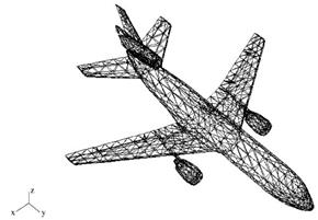
Figure 1. Geometrical model of a DC10 plane using 2317 flat facets
As a result of flat facet-induced error, some computer graphics applications, especially in the automobile and aerospace industries, and industries using computer-aided design software, require the usage of curved surfaces, which are often in the format of nonuniform rational b-spline surfaces (NURBS).
Using NURBS as an approximating surface set provides an accurate representation of a real object that employs significantly less information (on the order of a thousand curved surfaces), and mitigates the inherent problem of flat-facet approximation-induced artificial edges.
Figure 2 shows the same aircraft from Fig. 1,butitismodeled by NURB S surfaces. Only168surfaces are necessary to represent the object accurately, and no artificial edges are generated. The primary disadvantage of the NURBS representation is that the computational cost of the ray-tracing is much greater than that of the flat facets model. The details of this will be discussed later.
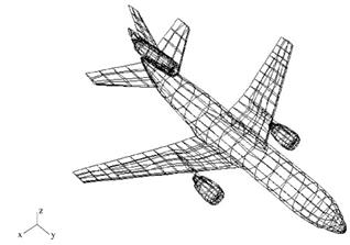
Figure 2. Geometrical model of a DC10 plane using 168 NURBS surfaces
Ray-Tracing Mechanisms. A ray-tracing mechanism is defined as a set of coupling rays that link a source with an observation point (see Fig. 3). As illustrated in Fig. 3, these rays can be a direct ray from the source to the observation point, simple effect rays, double effect rays, and higher-order effect rays. Simple effect ray-tracing mechanisms are the reflected rays, the transmitted rays, and the diffracted rays.
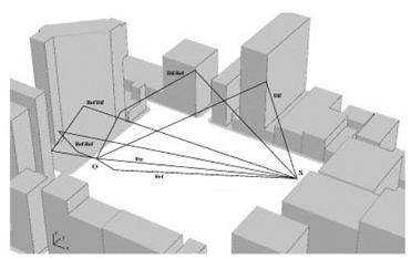
Figure 3. Example of ray-tracing mechanisms on an urban scene given the position of the source and the observation point. Only simple (direct, reflected, and diffracted rays) and double (double reflected, reflected-diffracted, and diffracted-reflected rays) effects are depicted in the figure for the sake of simplicity
Reflected rays are defined as rays that leave a source, are reflected in a facet, and then arrive at the observation point. Rays that link the source and observation point by transmission through a facet are transmitted rays. Rays that link the source and observation point by scene edge diffraction are diffracted rays. Double or higher-order effects are combinations of simple effects.
For example, a third-order ray can be a reflected-trans- mitted-reflected ray. The points involved in each ray are known as flash points. Shadowing is another relevant RTT mechanism; a ray is shadowed if any segments forming that ray are occluded by any of the scene facets.
When occlusion occurs, the ray must then be discarded because it does not contribute to the illumination of the observation point. If the ray mechanism under analysis includes transmission, then the transmission facet should not be considered in the shadowing test, and the contribution of that ray should be considered for the illumination of the observation point.
Among the aforementioned mechanisms, the most common are the shadowing and diffuse reflection of rays that leave illuminating sources. The shadowing discard, as not visible from an observation point, includes many facets of a scene. The diffuse reflection permits a visualization of all points on every surface visible from the observation point.
Transmission through surfaces (transparency), refractions in volumes, double, triple, and higher-order reflections on surfaces, may also be required for visualization. For RTT electromagnetic applications, the number of reflections, transmissions, and combinations of both is usually high, which require a different treatment. Reflections are treated as specular; however, if the surface is not smooth with respect to the wavelength, part of the energy is reflected in nonspecular directions.
Models can be used to compute the energy fraction reflected along the specular direction for ray tracing, but energy reflected along nonspecular directions is not used in RTT, which is a significant limitation of this technique in electromagnetic applications. Furthermore, these applications require an accurate evaluation of the path length for phase computation, because illumination is achieved using coherent waves.
Coherent waves can interfere destructively depending on their relative phase, whereas incoherent waves interfere constructively. Additionally, wedge-edge diffractions play an important role in these applications because of the broad angular expansion of the waves after diffraction. This phenomenon has been demonstrated to supply the illumination in many areas of a scene.
Date added: 2024-03-07; views: 779;