Descriptions of Hydrosystems. Block-diagram representation of the global hydrologic system
Hydrosystems is a term originally coined by V. T. Chow to describe collectively the technical areas of hydrology, hydraulics, and water resources including the application of economics, optimization, probability, statistics, and management. Hydrosystems has also been a term used for reference to types of water projects including surface water storage systems, groundwater systems, distribution systems, flood control systems, urban drainage systems, etc.
Hydrosystems, as used in this book, actually applies to both definitions. The premise is that hydrosystems engineering and management can be subdivided into (1) water supply engineering and management; and (2) water excess engineering and management. Modem multipurpose water projects are designed for water-supply management and/or water-excess management.
Water is a renewable resource that naturally (without human influence) follows the hydrologic cycle as shown in Fig. 1.1.1. The hydrologic cycle is basically a continuous process with no beginning or end which can be represented as a system. A system is a set of interconnected parts or components that form a whole. The components that form the hydrologic-cycle system are precipitation, evaporation, runoff, and other phases.

Fig. 1.1.1. Hydrologic cycle with global annual average water balance given in units relative to a value of 100 for the role of precipitation on land. (Chow, Maidment, and Mays, 1988)
The global hydrologic cycle represented as a system can be divided into three basic subsystems: the atmospheric water system containing the precipitation, evaporation, interception, and transpiration processes; the surface water system containing the overland flow, surface runoff, subsurface and groundwater outflow, and runoff to streams and the ocean processes; and the subsurface water system containing the processes of infiltration, groundwater recharge, subsurface flow, and groundwater flow. This division of subsystems within the global hydrologic system are shown in Fig. 1.1.2.

Fig. 1.1.2. Block-diagram representation of the global hydrologic system. (Chow, Maidment, and Mays, 1988)
Descriptions of Hydrosystems. Hydrosystems include surface water supply systems, groundwater supply systems, water distribution systems, urban drainage systems, floodplain management systems, and others. This section will present examples of various types of hydrosystems.
SURFACE WATER SUPPLY SYSTEMS. An example of a large comprehensive surface water supply system is the California State Water Project (SWP), which consists of a series of reservoirs linked by rivers, pumping plants, canals, tunnels, and generating plants, as shown in Fig. 1.2.1.
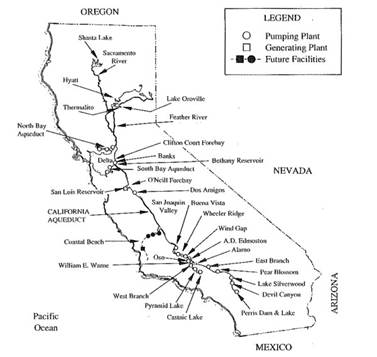
Fig. 1.2.1. California Stale Water Project (Sabet and Coe 1986a, 1986b; reprinted by permission in Coe and Rankin, 1989)
In northern California the Feather River flows into Lake Orovilie, the SWP principal reservoir. Releases from Lake Oroville flow through the Feather and Sacremento Rivers to the Delta. In the southern part of the Delta, the Harvey Banks pumping plant lifts water into the Bethany Reservoir where water is distributed to SWP’s South Bay Aqueduct and to the Governor Edmund G. Brown California Aqueduct, the principal conveyance feature of the SWP. The California Aqueduct is located along the west side of the San Joaquin Valley and flows into the San Luis Reservoir about 100 miles downstream. The aqueduct continues south and water is raised 969 feet by four pumping plants (Dos Amigos, Buena Vista, Wheeler Ridge, and Wind Gap) prior to reaching the Tehachapi Mountains.
The Edmonston Pumping Plant lifts the water 1,926 feet to a series of tunnels and siphons. After the Tehachapi Crossing, water enters the East Branch or the West Branch. The East Branch conveys water to Lake Silverwood where it enters the San Bernardino Tunnel and drops 1,418 feet through the Devil Canyon Generating Plant. A pipeline then conveys water to Lake Perris at the southern end of the SWP, 444 miles from the Delta. The West Branch conveys water through the Wame Generating Plant into Pyramid Lake and through Castaic Pumping/Generating Plant into Castaic Lake, at the end of the West Branch. Both simulation and optimization techniques are used by the California Department of Water Resources for the monthly operation of the five main SWP reservoirs (Coe and Rankin, 1989).
URBAN WATER SYSTEMS. On a much smaller scale the urban water system is another example of a hydrosystem. As shown in Fig. 1.2.2 urban water systems include various interfaces with the hydrologic cycle through water supply, discharging wastewater and drainage flows into receiving streams, and conveying of storm and flood water through the urban area. The urban water system can actually be divided into other basic systems such as the water supply system, the wastewater system, the urban drainage system, and the floodplain management system.
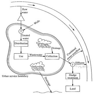
Fig. 1.2.2. Components of the urban water system
The water supply system can also be subdivided into systems such as the raw water pumping system, the raw water transmission system, the raw water storage, the treatment system, the treated pumping system, and the water distribution system. Many urban wastewater collection systems involve both the urban water runoff component in addition to the combined sewage overflow as shown in Fig. 1.2.3. Such a system includes the runoff, the transport, the storage, and the receiving water.
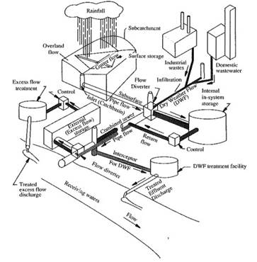
Fig. 1.2.3. EPA stormwater management model
GROUNDWATER SYSTEMS. Groundwater has been introduced through the hydrologic cycle. Groundwater systems (Fig. 1.2.4) are geologic formations, called aquifers, that are capable of storing and transmitting the subsurface waters. These aquifers have varying transmissivities, storages, and water quality properties that affect aquifer pumping and recharge. Groundwater systems can be developed as sources of domestic, industrial, and agricultural water supply. These systems can also provide temporary and/or long term storage and treatment of waste water.

Fig. 1.2.4. Groundwater system
An example of a groundwater system is the Edwards (Balcones fault zone) aquifer shown in Fig. 1.2.5, which extends along the narrow belt from Austin, Texas through San Antonio to Brackettville, Texas. The groundwater is used extensively for public water supply, agriculture, and industry. This aquifer is the water supply source for the city of San Antonio, Texas. In addition it originates several major springs that become recreation centers and also provide the base flow of downstream rivers. These spring fed streams flow into the San Antonio Bay, whose ecosystem is dependent on the freshwater inflows.
The present problem facing the Edwards aquifer is the threat of overdrafting of the annual replenishing rate. This aquifer has both unconfined and confined conditions. The confined portion is along the south and is the most productive and the unconfined portion is the recharge zone which yields small to moderate amounts of groundwater. The aquifer thickness ranges in depth from about 400 to 1000 feet deep. Due to high permeability of the aquifer, large volumes of water can move rapidly over wide areas and the response of water levels to high single pumping tends to be regionalized rather than localized.
Date added: 2023-11-08; views: 874;