Interoperability Impact of Signal Center Frequency
One of the very useful aspects of combining signals with a common center frequency is that after each signal is captured by the receiver’s antenna, the time delay through RF/IF filters, amplifiers, and cables is almost identical for each received signal. If the signals are digitized by a single A/D device using only one sampling clock, the time difference between the digitized signals can be assumed to be zero. For accurate navigation and positioning, it is not necessary to calibrate the time delay between signals. For timing receivers, depending on the needed accuracy, calibration from the antenna to the time signal output maybe needed, but not the time difference between received signals (other than accounting for the timing difference between system clocks).
There are two reasons for the minor exceptions to the “zero difference” assumption. One is the Doppler shift of each signal due to the relative velocity of the satellite and the receiving antenna. Each signal typically will have a different Doppler frequency offset. At 1575.42 MHz, the Doppler offset for an Earth-based receiver ranges from about —5 to +5 kHz. Figure 9.3 illustrates this by the width of the lines representing the GPS L1 center frequency and the 14 lines representing the GLONASS FDMA center frequencies. Superimposed in Figure 9.3 is the spectrum of the GPS C/A signal, with the first nulls at ±1.023 MHz.
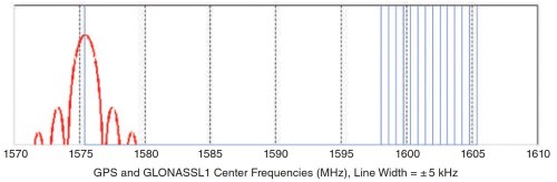
Figure 9.3. GPS L1 Center frequency and GLONASS center frequencies with ±5 kHz Doppler shifts. The GPS C/A signal spectrum is shown at the GPS L1 center frequency
The intent is to show that the Doppler shift is a tiny fraction of the spread spectrum bandwidth. The comparison is made because even narrowband receivers must process most of the L1 signal bandwidth. Typical consumer receivers have band- widths on the order of ±2 MHz or greater. Limitations of the Excel plot do not necessarily show how small the Doppler shift is compared to the spectral width of the C/A signal. Figure 9.4 shows this more clearly. The two lines representing the GPS center frequency are at 1575.42 MHz + 5 kHz and 1575.42 MHz - 5 kHz.
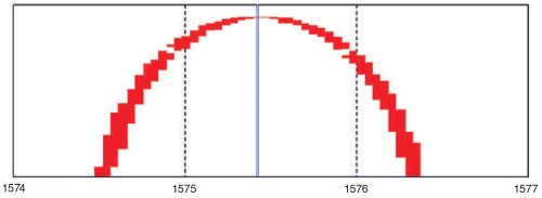
Figure 9.4. GPS L1 center frequency with ±5 kHz Doppler shifts and GPS C/A signal spectrum
Receiver components, especially filters and cables, have a variable time delay as a function of frequency. For almost every application, the time delay difference due to the relatively tiny Doppler shifts can be ignored. There may be a few applications in which even such tiny effects must be measured and calibrated to achieve the utmost precision.
The second and more significant reason for small time delay variations between signals is that the antenna itself is not time delay isotropic. Signals arriving at different azimuth and elevation angles suffer small time delay differences. The received carrier phase varies over 360° as a function of the satellite azimuth relative to the receiving antenna position. For the highest-precision applications, these variations are measured and mapped and corrections are applied when processing the signals.
For consumer applications, such small variations are negligible, especially when compared to the much larger sources of error, including multipath and uncorrected ionospheric and tropospheric refraction.
As illustrated in Figure 9.3, the center frequency offsets between GLONASS FDMA signals are enormous, especially as compared with Doppler frequency shifts. The frequency offset between GPS L1 and any of the GLONASS FDMA channels ranges from 22.6425 to 29.955 MHz. The frequency offset between individual FDMA channels ranges from 0.5625 to 7.3125 MHz.
These differences are large even compared with the span of the C/A signal spectrum. In fact, the spread between GPS and the FDMA channels is so large that most if not all receivers employ different RF/IF hardware, including different filters, for CDMA than for FDMA signals. This violates a main interoperability objective of “allowing navigation with signals from at least four different systems with minimal additional receiver cost or complexity.”
To achieve accuracy with an FDMA-only receiver, the filter(s) must be designed to minimize differences in time delay from one channel to another. A pre-calibration of these delays should be provided to the processing software, and a built-in test signal to calibrate the differences maybe needed.
When GLONASS FDMA is used with GPS, Galileo, Bei-Dou, and/or QZSS, a calibration of the individual FDMA delays can be made with respect to a position solution that is independent of GLONASS measurements. Although filter time delay variations can change over time and with temperature, as long as the calibrations remain valid they can be used to benefit from use of the FDMA signals. Because the additional coverage and accuracy obtained by adding GLONASS to GPS is so valuable, many receivers, from consumer devices to high-precision survey and machine control products are so equipped. Once many more reliable CDMA signals become available from other providers, the question will arise of whether the additional complexity of using FDMA signals will be justified.
This is why the emerging GLONASS use of CDMA is so significant. The frequency offset with GPS L1, L2, and L5 will not be eliminated. These differences will be 25.575, 20.46, and 25.575 MHz, respectively. (As factors of 1.023 MHz, the differences are factors of 25, 20, and 25, respectively.) However, having 1.023 MHz as the base for all GLONASS CDMA signals should simplify frequency synthesis in every receiver processing both GLONASS CDMA and other GNSS signals.
The frequency differences are large enough to warrant the use of two filters at each band, one for most GNSS CDMA signals and the other for the GLONASS CDMA signals. This requires a larger product size and more cost, but the cumbersome and suboptimal need to individually calibrate the time delay of each FDMA channel will be eliminated. In fact, the calibration can become one additional parameter in the positioning solution.
The relative time delay parameter between filters will be very stable, changing only slowly. In many applications, that parameter can be combined with the very stable system clock difference parameter. Once a solution is obtained, each one or the combination can be heavily filtered so as not to “waste” even one satellite signal in subsequent positioning solutions.
As shown in Figure 9.2, 1.023 MHz is the base not only for the GLONASS CDMA center frequencies but also for the spreading code clocks. The spreading code lengths also are multiples of 1023 chips. Clearly the intent is to be as interoperable as possible with most other GNSS signals even if the center frequencies are not identical.
Date added: 2024-08-26; views: 652;