Casting Process. Sand Casting. Die Casting
Cylinder heads for internal combustion engines place considerable demands on the mechanical properties of the materials in a temperature range beyond 150°C. The design latitude for the geometries in the cylinder head is severely limited by the components to be used in the cylinder head. Particularly when developing new cylinder heads for direct-injection diesel engines the complexity in the type and magnitude of the stresses occurring during operation has risen considerably.
To satisfy these more exacting requirements, the materials available for use have to be optimized and further developed. Any of a variety of materials may be used for cylinder heads, depending on the requirements profile and the casting process used. In addition to aluminum, cast iron materials are also used for industrial engines and utility vehicle power plants. In passenger car engines aluminum is used almost exclusively, with just a few exceptions.
Cylinder heads may be manufactured both from primary alloys— aluminum extracted from ore at the refinery—and from recovered alloys—recycled aluminum following melting and purification; these may be delivered as ingots or as liquids. Aluminum casting alloys are also used for heavily loaded diesel engines with direct injection, but not all the available casting techniques may be used with these cylinder heads.
At ignition pressures exceeding 150 bar it is necessary to use alloys that satisfy the following stringent demands:
- High tensile strength and high creep resistance between room temperature and elevated temperatures of about 250°C
- Great thermal conductivity
- Low porosity
- High ductility and elasticity at great resistance to thermal shock
- Good casting properties at low susceptibility to heat Assuring
The central area of the cylinder head near the combustion chamber and, in particular, all the webs located near the exhaust ports are subjected to severe thermal loading in a range of from 180 to 220°C, this in addition to mechanical loading.
The casting technique should be determined as soon as the concept for a new cylinder head is finalized. An early evaluation by the model shop and the casting department helps to avoid errors in the engineering phase. The job of the casting department is to influence cylinder head design to optimize casting for the rough component. The filling and solidification processes in the casting procedure are assessed largely from simulation.
These 3-D calculations give the casting department valuable information on problematic areas that might be anticipated right from the conceptualization phase. The geometry of the cylinder head can be modified to accommodate these areas before the first prototype is built. Considerable cost savings can be realized in the development process in this way.
The casting techniques used for engine blocks can also be used for cylinder heads. A brief review of the most commonly used casting techniques is provided below.
Sand Casting. Models and core boxes made of hardwood, metal, or plastic are used to replicate the later cylinder head casting inside the sand mold. The casting molds are normally made of quartz sand (either natural or synthetic sand) and binders (synthetic resin, C02).
The sand cores are formed in core casting machines into which the sand is introduced under pressure; the mix of sand and resin is compacted to create the core by applying heat. It is advisable to use the laser sintering processes when making sand cores in the prototype phase. Combining individual cores to form a core package and assembling this core package and the outer casting mold are handled mechanically and fully automatically, even when producing only limited numbers of castings.
Parting for the model, core, and mold in various planes and inserting cores in the casting mold make it possible to produce complex cast components with undercut areas. During the casting process, the hollow cavities between the outside mold and the cores are filled with molten metal. Following the filling process and after the metal has solidified, the casting is removed from the sand mold. The sand mold is destroyed here (which is why this is referred to as a “lost mold” process).
Following casting the rough part is cleaned, and the gate and risers are separated. In mass production operations, these steps are fully automated. Sand-cast components made of Al-Si alloys permit double heat treatment. The first heat treatment phase is found in controlled cooling of the casting while still inside the sand mold.
The second heat treatment takes place during time- and temperature-controlled exposure of the casting to heat in a kiln. These heat treatments increase the strength of the cast component and relieve inherent stresses created during the cooling process. The geometry of the components may include undercuts since the lost mold is used for only a single casting.
One advantage of sand casting is that the fabrication equipment can be set up quickly and economically when making small numbers of units. Cylinder heads for special types of engines, such as sports car engines, can be quickly realized; implementing changes during development is relatively simple and economical since plastic positives are used.
The low-pressure sand-casting process is suitable for prototypes and short production runs. Here the melt is introduced from below, through a riser, and into the sand mold; pressure at about 0.1 to 0.5 bar is applied to the molten metal (Fig. 7-81). This pressure is maintained during casting. Since solidification under pressure is almost directional, the structures in the cylinder heads are very fine.
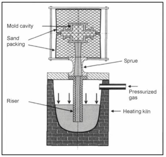
Fig. 7-81. Low-pressure sand-casting process
The Cosworth low-pressure sand-casting process is used for cylinder heads, too, because of great dimensional accuracy and strength, a compact structure, and freedom from pores. In accordance with the specifications for the process, an aluminum alloy, in the form of assayed ingots, is melted in a resistance electric furnace under a blanket of inert gas, Fig. 7-82.
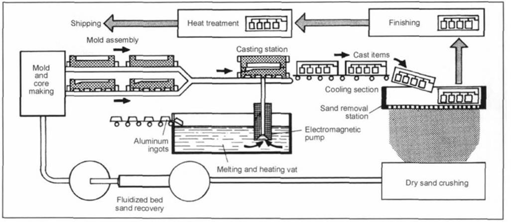
Fig. 7-82. Casting process developed by the Cosworth Company
The melts are buffered in a generously dimensioned holding kiln, once again blanketed with inert gas. Casting is affected with an electromagnetic pump that moves the molten aluminum upward to the sand mold, where it flows from below into the mold cavity. Just as in the low-pressure die-casting process, the pressure on the molten metal is maintained during solidification.
Programmable regulation of pump output makes it possible to set a delivery rate suitable to the particular shape of the cavity. Casting can be automated to a great extent; the finished molds are moved one after another to the casting station, above the electromagnetic pump.
The core package process has been used to manufacture cylinder heads for about 20 years now. In this sandcasting process a closed sand core package is assembled from several individual sand cores. Adhesives are normally used to hold these together, but screws may also be used. Core packages are used for cores of complex design, which cannot be made up in a single piece. In its original embodiment the core package process, based on the low-pressure die-casting principle using an electromagnetic pump, was limited to short production runs for cylinder heads because of its low productivity.
The latest approaches also point out perspectives for using this process in mass production once manufacturing facilities have been modified appropriately. The cast components do not fall below a temperature of about 500°C after casting through complete removal of the sand. Thus, they are cast virtually free of strains, giving the parts superior dimensional accuracy. Since each part is cast in a new, cold mold, practically no dimensional deviations are found such as those that occur in die casting, where the permanent molds are subject to wear.
Die Casting. About 90% of the cylinder heads made in Europe are manufactured by the die-casting process. The dies are permanent metal molds made of gray cast iron or hot-work tool steels and used to manufacture cast parts from lightweight alloys. Just as in sand casting, the sand cores are positioned inside the casting mold. Die casting can be subdivided into the gravity and low-pressure processes.
In gravity casting the mold is filled solely with the force of gravity acting on the molten metal and at atmospheric pressure. The casting process is used in partially or fully automated casting systems. In this casting process, in contrast to sand casting, the dies can be used many times. It is necessary only to make new sand cores for each casting cycle, which is referred to as lost-core casting.
Because of the use of sand cores, die casting, like sand casting, offers the advantage of greater freedom in the engineering design. Undercut areas are possible, in contrast to pressure die casting. Using steel as the die promotes fast and directional solidification of the molten metal; this is not the case in sand casting. The die is protected against the lightweight metal melt by applying a parting agent, also referred to as a refractory coating.
In comparison with sand casting, the die cast components exhibit a finer internal structure, greater strength, improved dimensional accuracy, and better surface quality. Both die castings and sand castings can be further processed with double heat treatment. In addition to the advantages of carefully defined control of cooling inside the die, which is the first heat treatment, additional heat treatment is often implemented. As opposed to sand casting, there may be no undercuts in the permanent molds since they are used over and over.
Most of the cylinder heads at the VW Corporation, for instance, are manufactured using this process. The combustion chamber side of the cylinder head is cooled by inserting one steel die per cylinder. The sprue is at the upper side of the cylinder head, and the molten metal fills the mold as it flows downward from this point. The area around the combustion chamber cools faster because of the cooled combustion chamber dies, and this increases strength in that specific area.
The casting process takes place on a turntable system with several stations; this reduces mass-production manufacturing costs to a minimum. The standard alloy used for this purpose is G-AlSi7MgCu0.5. Smaller runs are outsourced to suppliers. Similar processes are used there, and in some cases the cylinder heads are cast from below using special runners. The results are comparable in terms of the quality found in the final product.
A large number of cylinder heads is also produced with low-pressure casting, as is the case at the HONSEL Company in Meschede. This is one of the processes the casting department at BMW uses for their diesel engines and a majority of their gasoline engines. In much the same way as described above, the inductance-heated melt is pressed into the mold through a riser at a pressure of about 0.1 to 0.3 bar. The combustion chamber, at the bottom of the mold, is filled from below.
Here, too, the combustion chamber plate is cooled with air or water. The cavities for water and lubricating oil and the geometry required for the camshaft timing chain are formed with sand cores. The remainder of the geometric forms in the cylinder head are shaped with dies. Thanks to the low-pressure casting process, the surfaces at the cylinder head are densely compacted. This process is particularly good for diesel cylinder heads that are subjected to heavy loading.
A technique developed by the VAW Mandl&Berger Company is known as the Rotacast process. The entire mold is rotated during the casting process. This process is intended to achieve turbulence-free mold filling. The form is filled from below and, during filling, is rotated through 180° within a period of 15 s.
The charge passes into the mold through several, variable openings. Metallurgical studies have revealed that—with this process and the G-AlSi7Mg0.5 containing 0.19% iron—very good and highly reproducible structures are achieved, particularly in the area around the combustion chamber. When using the “LM Rotacast T6” alloy the mechanical properties with the 0.2 offset limit (Rm) in the combustion chamber area, at 272 MPa, are better than for the G-AlSi7MgCu0.5 alloy (gravity casting) at 260 MPa.
The exact values depend upon the casting process used and subsequent heat treatments. The Isuzu Company, for example, manufactures cylinder heads using the Rotacast technique.
Date added: 2024-04-24; views: 722;