Machining and Quality Assurance
Mass-Production Manufacture. Cylinder heads are machined in mass-production operations on transfer lines or at linked machining centers, which make it possible to respond more flexibly to changes. A trend toward machining at sequential machining centers is emerging. Here the rough component passes through several machining stations, one following another.
It is necessary for each station to adhere to the prescribed cycle time. To limit the high overall investment costs, as many machining phases as possible are implemented at any given station. When developing a cylinder head, manufacturing planners should be integrated into the project following the tenets of simultaneous engineering in order to take into account the needs of manufacturing at an early date, all with the goal of achieving economical realization.
Changes to the cylinder head that have to be implemented retroactively at transfer lines are expensive and time consuming since the entire manufacturing process has to be interrupted. Because of the needs found in mass production, it is often necessary to adopt compromises at cylinder heads that restrict developers’ design latitude.
Prototype Manufacturing. Machining centers are normally used to work small production runs and prototypes. Often these individual stations are standardized machine tools that can be flexibly programmed and allow changes in the cylinder head to be implemented quickly. The machining costs are higher in comparison with mass production. The combustion chambers are in some cases machined to achieve better uniformity in the combustion processes. It is possible to machine the transitional areas from the gas exchange ports to the combustion chamber and the complete port shapes.
Quality Assurance for Cylinder Heads. Failure of a cylinder head in the field often results in complete destruction of the engine. The goal for both the casting and the machining is to achieve a high quality standard for the customer, so the entire cylinder head is tested 100% for leaks. Spot checks by measuring components are standard procedures in quality control. It is imperative to minimize the reject rate in manufacturing.
Computer-assisted tomography, known from the field of medicine, can be used to examine cylinder heads and to check the wall thicknesses, slice by slice, for compliance with the specified shapes and dimensions. Such examinations are standard, particularly for thin walls in a range of about 2.5 mm, as required in racing engines for reducing weight; see Fig. 7-87.
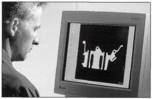
Fig. 7-87. Computer tomograph section of a cylinder head
Figure 7-88 shows verification measurements for a cylinder head using a coordinate measurement unit. This makes it possible to measure channel inside geometry, too. The channel surface can be traced point by point to form clusters of individual points. Deviations from the geometry described in the CAD data records can be detected.
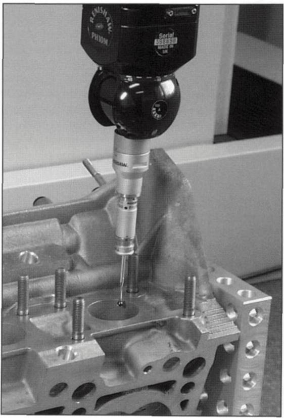
Fig. 7-88. Digitizing an intake channel
Using the points transmitted to CAD systems makes it possible to apply reverse engineering methods to establish surface areas based on the cluster of points, which can also be used for three-dimensional flow simulations. These techniques are particularly valuable in association with direct-injection engines since here even slight dimensional deviations can have considerable effects on the engine.
Date added: 2024-04-24; views: 718;