Lost-Foam Process (Full Mold Process). Pressure Die-Casting Process
The full mold (or lost-foam) process is used for mass production in the United States. At BMW’s Landshut plant this process was used for the first time in a six-cylinder, inline gasoline engine. The lost-foam process may also be considered a special form of the sand-casting process. The key steps in manufacturing a cylinder head are shown schematically in Fig. 7-83.
First, the polystyrene granulate is warmed, expanded to about 30 times its original volume, dried, and stored. In the first step in the casting process the contours, from which the cylinder head is assembled in various layers, are foamed using the polystyrene material. For dimensional stability the foaming tools are cooled with water. Grippers remove the foam blank, which then cures on a conveyor belt.
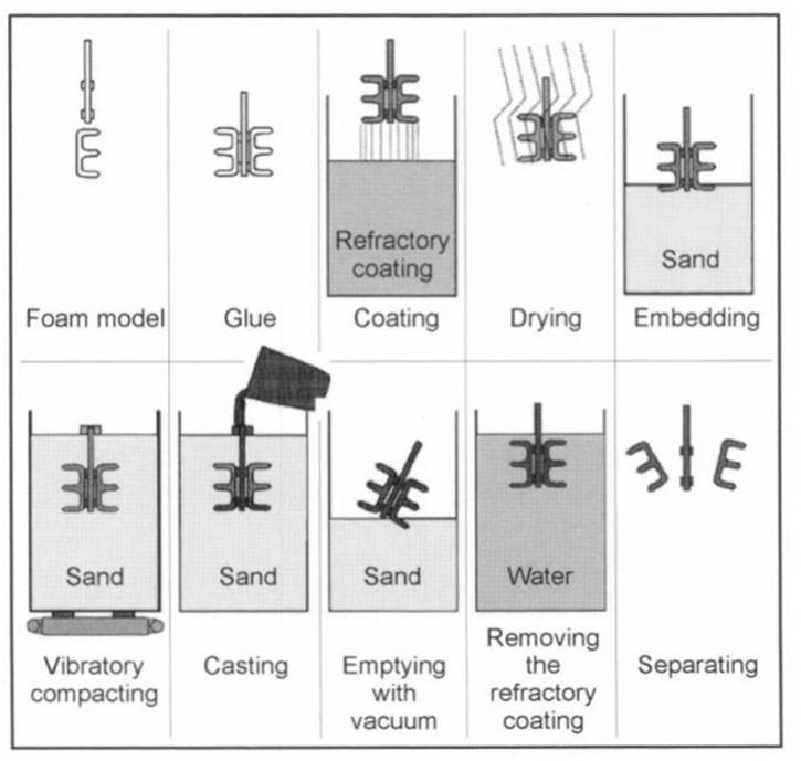
Fig. 7-83. Lost-foam process
The sum of the foamed contours represents the exact geometry of the cylinder head, taking into account thermal shrinkage. The individual contours are now joined at two stations with hot-melt adhesive. The positive model of a cylinder head comprises five polystyrene layers glued together in this way. Two cylinder head models are glued together with the sprue and runners to form a cluster. At the third station, this cluster is immersed in a water-soluble ceramic refractory coating.
The unit is rotated to better homogenize the application of the refractory coating. At the fourth station, the cluster is dried in a stream of dry, heated air. This extracts the water to form a dense, gas-permeable refractory coating. In the next step the cluster is inserted into the casting frame, and unbonded quartz sand is filled loosely around it.
The sand is compacted at the sixth station by vibration. Casting then follows. A charge of molten aluminum is prepared and poured into the mold automatically using a casting ladle. The polystyrene retracts and gasifies during filling. At the eighth station, the mold is removed, and the sand is taken out of the casting frame. The refractory coating is removed in a water bath, and in the final step the individual cylinder heads are separated from the cluster.
The casting process itself demands familiarity with this technique, too. There is a great range of freedom in the engineering design for the cylinder head. Bores in the cylinder head, down to a minimum wall thickness of 4 mm, can be cast directly with the cylinder head. Changes in the course of the production run can be implemented at the tooling relatively easily and thus at favorable costs, since the tooling is made of aluminum.
At a cycle time of four heads in 3 min, this system offers production capacity of about 330000 cylinder heads per year, Fig. 7-84. In consideration of the high strength requirements for direct-injection diesel engines, this process has not been used to date in mass production for this particular application.
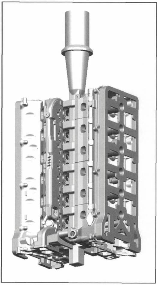
Fig. 7-84. Lost-foam cylinder head casting model, BMW
Shown in Fig. 7-84 is the polystyrene casting cluster used by BMW for the first time in Europe to cast a cylinder head in the lost-foam process. The material used here is G-AlSi6Cu4 (aluminum alloy 226). A thermally decoupled, secondary air channel was integrated into the exhaust side for the U.S. versions.
This process makes it possible
- To cast oil channels in virtually any desired shape
- To obtain water cavities with elaborately shaped flow control fins
- To implement curved intake and outlet ports
- To achieve markedly narrower tolerances in the combustion chamber area
- To use only a single foaming die for the duration of the production run
- To reduce significantly the amount of postcasting machining work required for the cylinder head
Pressure Die-Casting Process. Permanent molds made of hardened, hot-work tool steels are used in the pressure die-casting process. The plug has to be coated with a parting agent or refractory coating before each casting cycle, also known as a “charge.” In contrast to sand casting and die casting, no cores can be inserted into the mold since the lightweight metal melt is introduced into the casting form at high pressure and high speed.
The pressure level depends upon the size of the cast component and as a rule ranges from 400 bar to about 1000 bar. As in low-pressure casting, this pressure is maintained during solidification. When casting larger components, the two halves of the casting mold are cooled for directional solidification and quicker cooling of the casting. Once the casting has solidified the mold, comprising fixed and moving components and possibly moving sliders, is opened and the casting is demolded with ejector pins.
This process can be used only for air-cooled cylinder heads such as those used with small engines.
In contrast to sand casting and die casting, pressurized die casting provides the most precise reproduction, as well as the greatest precision in the cylinder head geometry. Thin-walled castings with close dimensional tolerances, great exactness of shape, and superb surface quality can be fabricated. Exact casting of eyes, bores, mating surfaces, and other surfaces is often possible without subsequent machining.
Pressure die casting, when compared with sand casting, die casting, and low-pressure die casting, offers the highest productivity since almost all the easting and mold movement processes are fully automated. The drawbacks are the limited engineering freedom for the cast component, since undercuts are not possible. Air or gas bubbles that might be trapped in the casting preclude double heat treatment, as for sand casting, die casting, and low-pressure die casting. This process is not suitable for mass production of water- cooled passenger car engines.
Date added: 2024-04-24; views: 917;