Model and Mold Construction
When making the casting models, cores, dies, and all the casting tooling, almost all the parts are generated as models on the basis of 3-D CAD data throughout the CAD/CAM process chain. Thus, the geometry data are more reproducible and the response to change is more flexible. With the creation of the cylinder head design all the CAD models required for model making can be derived, from the CAD rough casting model to the fully machined component.
Here a carefully designed data management system is required to maintain transparency so that everyone participating in the project is kept informed of changes and so that changes at the CAD cylinder head component are reflected in all the data records required for model and tool making.
The model shop specifies all the traditional details such as mold sectioning, drafts, casting shrinkage, supplements for manufacturing, and any deformations that might be expected in casting; these are taken into account in the CAD model. An early and lively exchange of experience with the cylinder head engineers pays off in the long run. The model building activities vary, depending upon whether designing for prototypes or mass production and upon the choice of casting processes.
The low-pressure sand-casting process used by the Becker Company is superbly suited for small production runs and prototypes. Figure 7-85 shows a core plug (above) and the package used for a water jacket core surfaces and the so-called core markers that make possible exact alignment and sealing of the cores.
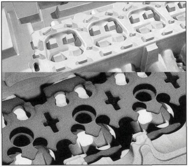
Fig. 7-85. Core mold tool and package for a water jacket core, by Becker
These cores are CNC milled in a special plastic resin, in only a few days, on the basis of the 3-D data. In the casting department these cores are filled with sand to which bonding resin has been added; this cures in a short period of time without further treatment. The sand core thus removed from the reusable core mold tool now exhibits the negative contour of the ultimate cast part. A special version here is the so-called sand laser sinter core, which can be made, layer by layer, directly from 3-D CAD data. No core mold tools are required here.
Cores for detailed interior contours such as the water jacket or oil-carrying cavities are especially suitable for this process since manufacturing a core mold tool for these cores is both costly and time consuming. Finally, all these core segments (both conventional and sand laser sintered) are assembled to create the core package, and molten material is then poured around it in the low- pressure casting process. A core package can be used for only a single casting.
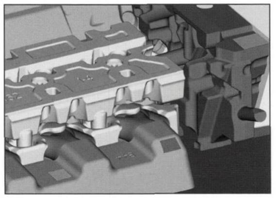
Fig. 7-86. Model of a cylinder head for an eight-cylinder BMW engine
A section of the overall core is shown in Fig. 7-86 for a cylinder head made by BMW for an eight-cylinder engine, using the low-pressure casting process. All the cores are made of sand. The core frames required for this purpose are made of steel for mass production work. The spaces between the core segments are filled with molten aluminum. During the development stage, the sand cores are made as rapid prototyping models, used to evaluate the overall geometry.
In the lower section of the illustration one sees the combustion chamber plate, shown in dark gray. To the right of that is the core for the timing chain case. In the foreground is the exhaust channel core package, which projects into the water jacket core. Located above this is the core for the oil cavity.
Date added: 2024-04-24; views: 785;