Shapes Implemented for Cylinder Heads
Cylinder Heads for Gasoline Engines. Four-cycle engines are discussed here. The cylinder heads illustrated here provide a selection from the multitude of valve train concepts found on the market, which have considerable influence on head geometry. The first example in Fig. 7-89 shows a two-valve cylinder head with roller cam followers made by BMW. This compact cylinder head concept is used in four- and twelve-cylinder engines.
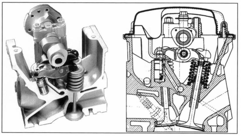
Fig. 7-89. Two-valve cylinder head for the BMW V-12 engine with roller-type cam follower
The head for the V-12 engine shown here is designed to be reversible and thus is identical for both cylinder blocks. To minimize friction, roller cam followers made of precision castings are used. This choice reduces friction in the valve train by as much as 70% when compared with the cylinder head without rollers, previously used. For weight restrictions, a hollow camshaft was developed using the process devised by the Siiko Company.
Pushrods with hydraulic adjustment are often used in mass-production engines. Figure 7-90 shows as an example a four-valve cylinder head crafted by BMW for use in a V-8 engine. Longitudinal bores are provided in the unitized cylinder head to supply oil to the valve lifters; after casting these channels are drilled into, from the outside, near the valve lifter bores.
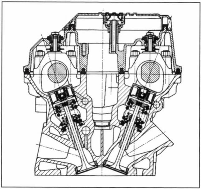
Fig. 7-90. Four-valve cylinder head with pushrods made by BMW
In V-block engines with hydraulic pushrods the oil requirements in the cylinder head and the danger of oil foaming due to camshaft rotation are considerable so that drains of sufficient cross section have to be provided for oil to return through the engine block and to the oil pan. In this cylinder head, six return ports are provided for each bank of cylinders.
The diameters of the intake valve disks are 32 mm for the three-liter engine and 35 mm for the four-liter engine; the exhaust valves measure 28.5 and 30.5 mm in diameter, respectively. Valve stem diameter is just 6 mm. The angle between the port and the valve is 39°45' on the intake side and 55°45' on the exhaust side.
The intake and exhaust valves form an included angle of 39°30' and thus make possible a very compact, crowned combustion chamber. The spark plug is located at the center, between the valves. The valve cover is mounted elastically and thus is largely acoustically decoupled. The combustion chambers inside the cylinder head are machined throughout to maintain close tolerances for the volume.
The longitudinal-flow cylinder head is cast from aluminum alloy 226. For weight limits, the head is not designed to be reversible in this eight-cylinder engine. Both variants of the cylinder head are manufactured at a single production line and arrive fully assembled at the final installation point.
Figure 7-91 shows a four-valve cylinder head concept using push rods in a multisection design. Separate bearing strips are provided for the camshafts and the push- rods, both on the intake and on the exhaust sides. Thus, the cylinder head, when in mass production, can be made using die casting since there are no undercuts in the upper area of the cylinder head.
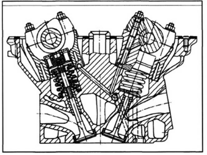
Fig. 7-91. Multisection, four-valve cylinder head made by BMW
An example of a four-valve cylinder head with roller cam followers is depicted in Fig. 7-92. This cylinder head, made by BMW, is a further refinement of the head illustrated in Fig. 7-91. The objective in reworking the valve train was to reduce friction in the cylinder head, which was previously fitted with pushrods. Hydraulic compensation is affected here by static adjustment elements.
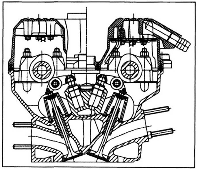
Fig. 7-92. Four-valve BMW cylinder head with roller cam followers
Positioning the play adjustment unit in the stationary part of the valve train makes possible lower spring forces, because of the reduced oscillating masses, even though the valve stroke and opening period are retained. At the start of engineering, manufacturing operations had specified that the existing production line was to be retained. Thus, the valve angles and positions and the camshaft bearings were kept from the previous design.
The scope of changes is thus limited to eliminating the bearing strips with the pushrod bores, the mounting bores for the compensators, which were arranged in a cloverleaf pattern around the spark plug, and the oil supply. Casting the camshaft bearings in place also lent stiffness to the cylinder head. The intake and exhaust ports and the combustion chamber were taken over without modification from the previous cylinder head.
Three-valve cylinder head concepts are used on the V-block engines made by DaimlerChrysler, Fig. 7-93. These cylinder heads use an overhead camshaft and roller rocker arms for valve actuation. Two spark plugs are used in each combustion chamber for faster bum propagation. In its eight- and twelve-cylinder engines, DaimlerChrysler incorporates cylinder cutout in this rocker arm concept, in the interest of reducing fuel consumption.
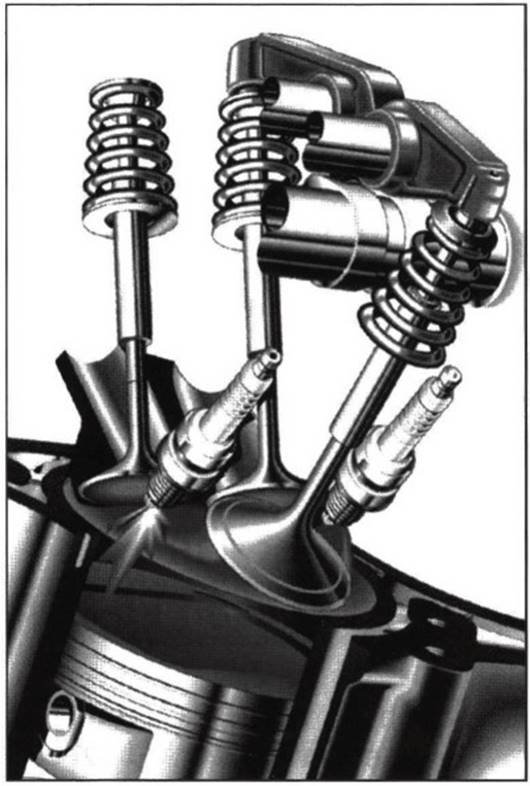
Fig. 7-93. Three-valve cylinder head made by Daimler-Chrysler
Four cylinders are shut down in the eight-cylinder version and six in the twelve-cylinder version. Positioning a camshaft shifter is made more difficult by this single-camshaft solution. Because of the relatively heavy rocker arm, this cylinder head concept is not suitable for concepts involving high engine speeds. The overall concept is, however, more economical than a four-valve arrangement with two camshafts.
In 1994, with the introduction of its A4 series, Audi built for the first time a five-valve cylinder head in passenger car engines. This cylinder head has been adopted throughout the VW Corporation for four-, six-, and eight- cylinder engines, Fig. 7-94. With the exception of the eight-cylinder engine that uses roller cam followers, these engines employ pushrods with hydraulic compensation.
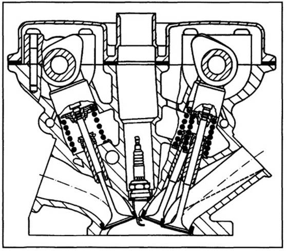
Fig. 7-94. Five-valve cylinder head made by Audi
For geometric reasons (the valve stem centerline would otherwise intersect the camshaft) the angle for the center intake valve differs from the other two. The valve angle for the outer intake valves is 21.6°, that for the center valve is 14.9°, and the exhaust valve angle is 20.2°. To improve force transfer at the head bolts, a bushing is screwed into the cylinder head; thus, the collar on the head screws can be kept small.
This effect helps alleviate the tight geometric situation at the cylinder head. In addition, the camshaft clearance can be kept at 129 mm since the bolts pass close by the camshafts. This is a one-piece cylinder head made up in gravity die casting. Similar five-valve designs had been used prior to their debut at Audi in one-, two-, and four-cylinder motorcycle engines made by Yamaha.
Date added: 2024-04-24; views: 887;