Cylinder Head Engineering. Laying out the Rough Dimensions
The cylinders’ bore and spacing determine the basic layout for the cylinder head. As a rule, the number of valves per combustion chamber has already been specified for new engineering. The minimum wall thickness required by manufacturing constraints and the necessary degree of stability narrows the space available for installing valve train components.
Since the number of camshafts is specified at the outset of engineering work, it is then necessary to specify the locations and arrangement of the valve train components, taking the geometry of the gas exchange elements such as the ports and combustion chamber into account. Studies then follow to determine how the rough dimensions of the cylinder head change when parameters such as the valve angle, unrestricted valve flow area, or design of the gas exchange ports are modified.
Laying out the Rough Dimensions. One way to establish the basic cylinder head geometry is to prepare rough engineering sketches for the valve train components. This is done with CAD support. Parameters can be assigned to the components’ individual geometric dimensions while doing so. Varying certain dimensions such as the valve angle, valve spring installation dimension, location of the camshafts, or spark plug length enables a rough evaluation of the overall concept.
Depicted in Fig. 7-70 are rough dimensions for a parameter study used in engineering a five-valve cylinder head with pushrods. This cylinder head incorporates three intake and two exhaust valves. The spark plug is shown at the center of the combustion chamber. Indicated beneath the cam geometry shown there is the installation space required for the pushrods. The locations of the head bolts, which also require a certain amount of free space for installation, restrict the latitude for varying the valve angle.
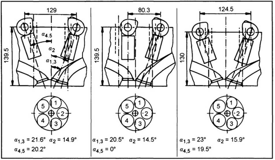
Fig. 7-70. Study on the basic geometric design of a five-valve cylinder head
Accessibility to the head bolts after the head has been completely assembled is mandatory for almost all engines because of manufacturing and maintenance requirements. Illustrated in the figure at the center, for example, is the situation in which, with a vertically suspended exhaust valve having a valve angle of 0°, the head bolts are located outside the camshaft axis for accessibility. In a V-block engine this type of cylinder head design provides more space on the exhaust valve side for the design of the exhaust components. Exhaust routing in the manifolds could be optimized.
These studies help in cylinder head development by allowing better evaluation of the overall effects on the engine. Using parametrized assumptions in the CAD system can, particularly in this development phase, make it possible to examine the basic cylinder head geometry with regard to its effects on the engine as a whole. Concept comparisons between pushrod and cam follower designs can also be carried out very well in this way.
One criterion for selecting the valve angle and the location and size of the valves is the determination of the unrestricted flow area around the valve disk. This is the unrestricted area available for gas exchange, as a function of the valve stroke, as described by Dong. To influence engine breathing, an attempt is made, in coordination with the remaining potential geometric configurations for valve train components and gas exchange runners, to make this area as large as possible. Structural requirements and values resulting from experience—such as the width of webs between the runners—have to be maintained.
In basic examinations of the geometric layout to preassess the situation regarding valve angle geometry, it is possible to compare variations with one another both quickly and simply. Concept studies using various numbers of valves can be carried out quickly and easily. To ensure that these studies can be completed quickly, in the early phase of cylinder head conceptualization, simple PC programs should be used, as is mentioned in Refs.
Depicted in Fig. 7-71 are examples of the parameters that are pertinent to the basic design of a six-valve cylinder head. Minimum web widths between the valves have to be maintained for both cooling and cylinder head strength. One objective here is to incorporate the largest possible valve diameters. The results of such examinations are geometric magnitudes such as the utilization of available surface areas.
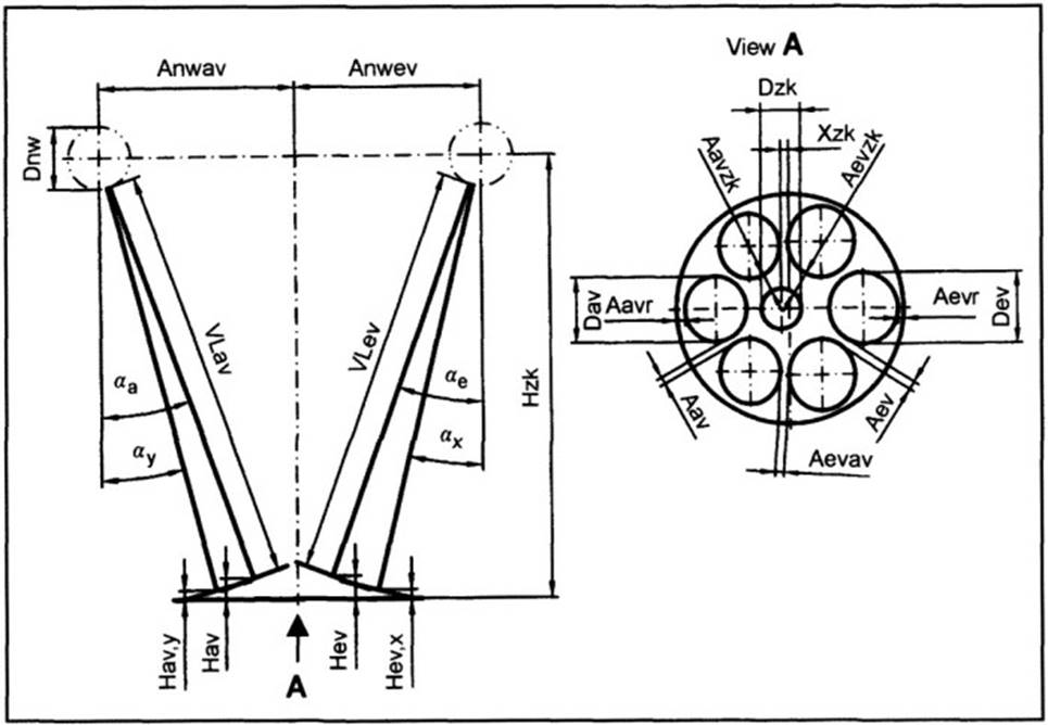
Fig. 7-71. Study to establish geometry for the valve cross section
This term is understood to be the quotient of the total intake or exhaust surface to the surface area for the cylinder bore. The results vary in dependency on the cylinder bore; when interpreted, this information gives differing numbers of valves. This phase of cylinder head development is particularly exciting since specifying the number of valves at a predetermined cylinder bore has decisive impact on cylinder head design.
Date added: 2024-04-24; views: 860;