Oil Pan Design. Crankcase Venting
Oil Pan. The oil supply for passenger engines today is provided almost exclusively with a wet sump lubrication design. In such engines the oil pan forms the bottom termination for the engine block, Fig. 7-66.
The most important of the oil pan functions are:
- Serving as a container to receive the motor oil when oil is first installed and as the collecting basin for motor oil returning from the bearings and lubrication points.
- Enclosing the crankcase it serves and, in specially engineered oil pan types, serving at the same time to stiffen the engine and transmission assembly.
- Taking the threads for the oil drain plug and the dipstick guide tube and often housing, in addition, an oil level gauge showing the oil fill in the vehicle.
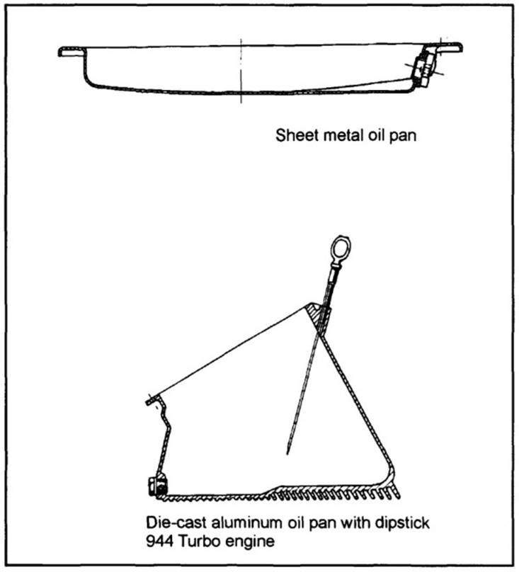
Fig. 7-66. Oil pan
Oil Pan Design. In mass production engines the oil pan is normally a singlelayer, deep-drawn component made of sheet steel. To improve acoustic properties, a design has recently been introduced that incorporates two layers of sheet steel with a plastic film between them.
Used in conjunction with large-displacement engines incorporating cast iron or aluminum engine blocks are oil pans made of Al-Si alloys, manufactured by die casting or pressure casting. These oil pans are usually an integral component in a stiff engine and transmission assembly. This is achieved with a stiff design for the oil pan side walls and, primarily, with an integral flange at the clutch end of the engine, as the connection to the transmission flange. This design makes a significant contribution to stiffening the engine and transmission group and, consequently, to better acoustic properties.
Oil pans made of aluminum alloys are made in single- and two-component versions. Two-part oil pans compose an upper section made of a lightweight metal and a lower section made of sheet steel and bolted to the upper section.
The steel component can be changed more economically in case of deformation (if the car bottoms out). In comparison, an oil pan made entirely of aluminum would have to be completely replaced if deformation occurs.
Today, this advantage is only of subordinate significance because of the underbody claddings being used more frequently to enclose the engine.
Crankcase Venting. During reciprocating engine operation, gases (the so- called blowby gases) from the combustion chambers pass through the gap between the cylinder and the piston and/or piston rings and into the crankcase.
The blowby gases contain, in addition to unbumed fuel components, the complete spectrum of emissions, identical to the exhaust gas. The hydrocarbon (HC) concentration in the blowby gases may, depending on the engine’s loading situation, be many times the concentrations contained in the exhaust gases. The blowby gases mix, inside the crankcase, with motor oil, which is present there in the form of oil vapor.
The pressurized blowby gases (the volume of which depends on engine loading) and the reciprocating motion of the pistons create overpressure (proportional to engine speed) below the pistons in the crankcase. Since the crankcase is joined with the cylinder head (by channels for oil return, crankcase ventilation, and a timing chain case, which may be present), the overpressure also prevails at these points inside the engine.
In the early years of engine construction, this pressure was relieved by venting the mix of blowby and untreated motor oil into the atmosphere. In response to newer legal requirements, controlled, closed crankcase ventilation systems have been in use for some time now.
Positive crankcase ventilation passes blowby gases, largely free of motor oil, into the engine’s fuel intake system, ensuring that virtually no overpressure is present inside the engine.
Conventional Crankcase Ventilation. A conventional crankcase ventilation system (Fig. 7-67) carries out the following essential functions.
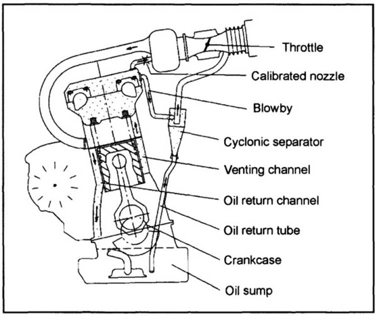
Fig. 7-67. Conventional crankcase ventilation
The blowby gases, mixed with oil, pass out of the crankcase, through one or more channels, to the highest point in the engine (normally inside the cylinder head).
These channels may be integrated into the engine block casting or may take the form of a channel (hose, tubing) located outside. The gas is introduced into the cylinder head at one or more points that are protected against oil spray. Oil separation is affected: Separating the motor oil swept up with the blowby gases.
One distinguishes among various arrangements and types of oil separators: those that are mounted in the cylinder head, those that are integrated into the valve cover, or those that are realized as a separate settling space in the crankcase. The effective surface area available for oil separation is often enlarged. This was done in the past with steel mesh and today with expanded sheet metal. Another option is to locate the oil separator, in the form of a cyclonic oil separator, outside the engine.
The arrangement and type depends on many criteria, including the engine design, the available installation space, and, finally, the engineering principles adopted by the engine manufacturer. Thus in V-block engines, for example, oil separators may be integrated either partially or completely into the engine block, in the space between the cylinder banks, or situated in this space as a separate, external oil separator.
The blowby gases, from which oil has been removed, are then introduced to the fuel intake system at a point where a vacuum will prevail at virtually all the engine’s operating states—upstream from the throttle, for instance.
In the past—in engines fitted with carburetors, for example—the crankcase ventilation tube terminated in the air filter case, whereas today, in fuel injection engines, the crankcase ventilation tube terminates just upstream from the throttle in order to avoid soiling the air volume sensor and the idle speed stabilizer.
The crankcase is joined with the fuel intake system, downstream from the throttle, by a tube to create a vacuum in the crankcase housing. An integrated, calibrated choke limits the effective vacuum level.
Excessive vacuum or pressure in the engine block can lead to failure of the engine sealing system (crankshaft end seals, oil pan gasket, etc.). Where vacuum is excessive, unfiltered air can enter the engine, triggering accelerated aging of the oil due to oxidation and sludge formation. Excessive pressure can cause engine leaks.
Ensuring the integrity of system functions depends upon the calibration of the choke (affected during optimization work) used to limit the vacuum present in the engine.
When the engine is not yet at normal operating temperature, the blowby gases contain fuel and water vapors, which can lead to engine icing. Icing is avoided by routing hoses in a suitable configuration to avoid creating a siphon and by other measures as indicated.
Date added: 2024-04-24; views: 799;