Valve Train Design. Cooling Concepts
The discussion as to which valve train concept is the best for a particular engine is one that we will not go into here. The engines’ requirements profile—which depend on its use—results in differing engineering strategies and, in turn, in differing valve train concepts. One does observe, however, a trend toward roller-actuated cam followers or rocker arms. These designs have the lowest friction valves for the individual valve trains.
But these solutions, in comparison with sliding cam follower concepts, are heavier; consequently, they are not used in sports car engines, for example. The goal here is to keep the masses in motion as small as possible and to minimize elasticity, which is why concepts using mechanical valve play adjustment are used in such engines.
The design of the valve train takes high priority in cylinder head development. In new developments pushrod concepts have proven their superiority to cam follower concepts. The installation situations for the valves are different. Different valve guide lengths have been worked out through time for pushrod and cam follower heads. Cam follower timing requires a better, and thus longer, valve stem guide than a pushrod concept since the push- rod itself has a guide.
The valve length, in turn, results from the installation length required for the valve spring. During new developments, these mutual interdependencies result in increased employment of simulation techniques during the predevelopment phase in order to keep the number of prototypes required for testing as small as possible.
Taking the refinement of the valve train for a BMW six-cylinder engine as an example, Fig. 7-75 shows the development steps undertaken over several model years in efforts to reduce the weight of the valve train.
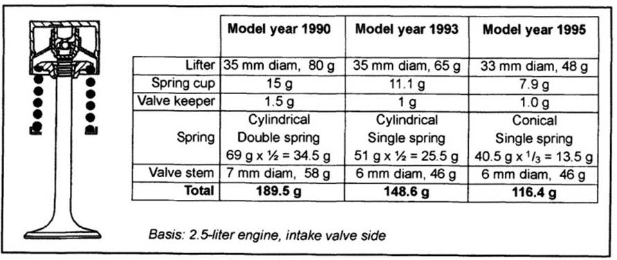
Fig. 7-75. Development steps for reducing weight in valve train components
To keep the valves from lifting at high engine speeds, the valve spring has to be built for a minimum force of F1 and the shape of the cam lobe has to be selected to suit. The required spring force and the associated spring geometry determine the minimum installation space for the springs. To limit spring force F2 at maximum valve stroke, the primary thrust in valve train engineering is to keep down the masses that act on the valve.
Cooling Concepts. In discussing cooling for the cylinder head, differentiation is made where water cooling is used, among cross-flow cooling, longitudinal flow cooling, and a combination of these two types. In cross-flow cooling the coolant flows from the hot exhaust valve side to the intake valve side; in longitudinal flow cooling the coolant flows parallel to the long axis of the cylinder head. The objective in cooling is to equalize temperature distribution within any cylinder head segment at a low level and to create uniform cooling conditions for all the cylinder segments.
Moreover, the top of the combustion chamber and the valve webs are to be generously supplied while at the same time keeping pressure loss throughout the cylinder head flow pattern as small as possible. The coolant passes from the engine block, through several transfer ports and the head gasket, into the lower face of the cylinder head.
The shape, location, and size of these transfer ports have to be harmonized appropriately. The coolant flow calculations described in Section 7.8.2.9 represent the state of the art. Only by simulation can problem areas such as the webs between the exhaust ports or the area around the spark plugs be engineered for complete reliability.
Date added: 2024-04-24; views: 702;