Computer-Assisted Design
A large number of calculation techniques are used today to dimension cylinder head geometries. With the early employment of calculations—even prior to the concept phase—calculation findings can be utilized in the initial cylinder head prototypes. This makes the steering of subsequent development steps more effective, and in this way the number of components used in testing can be reduced. Ongoing verification of calculations against test results continues to be necessary.
Computer support ranges from rough component dimensions and detailed design to optimization and simulation calculations. The target criteria for new engines—improved environmental compatibility, reduced exhaust emissions and fuel consumption, and improved performance, product quality, and ride—can be better satisfied through technical calculations.
Before the first prototypes are fabricated, the calculations are devoted primarily to specifying the valve, combustion chamber, and gas exchange port geometries. To a greater extent 3-D CAD data for the head geometry, once it has been prepared, can be used directly for technical calculations. During the development of a cylinder head in construction stages—understood to be differing cylinder head component development stages—technical calculations start right at the outset of development.
During the course of development, the largest share of calculations are performed in the first construction stage. The goal here is to provide support in identifying and defining the concept for the main cylinder head geometries. During testing in subsequent construction steps, technical calculations are used more to lend precision to the concept and to specify details. Calculation activities decline the closer the design gets to mass-production launch.
At this point we mention briefly only a few activities that play a vital part in dimensioning the cylinder heads. Technical calculations contribute to making it possible to interpret, in a more understandable fashion, the complex processes involved in cylinder head development.
The PROMO program is used to calculate the gas charge exchange. Here dynamic gas flows in the intake and exhaust systems of aspirated and turbocharged systems are calculated. The gas exchange components in an engine, with its intake and exhaust systems, are assembled to form a virtual model. Events associated with flow, such as pressure fluctuations or mass flows, can be analyzed at various points in the engine. The program provides information on the characterizing values to be expected for the engine, such as charging efficiency, maximum torque, or power output for a particular engine configuration.
The core for calculations is embedded in an interactive graphic user interface from which data record conditioning and result evaluation are undertaken. By establishing the geometry for the ports in the cylinder head, the PROMO program is particularly well suited for initial dimensioning of the gas exchange components in the early concept definition phase, and, in particular, for laying out the timing. In this way it is possible, when developing cylinder head concepts with variable valve control, for example, to minimize the scope of costly trials
In engine development the program also delivers findings on
- Intake manifold dimensions
- Concepts for switching and resonance intake manifolds
- Evaluation of cam lobe contours and timing
- Estimating the potentials of various concepts for variable valve timing
- Evaluating different port shapes
- Exhaust manifold design in regard to length and diameter
In addition to this, three-dimensional flow simulations are conducted to design the intake and exhaust ports and the combustion chambers in the cylinder head and pistons. The charge motions are simulated on the basis of the CAD description of the port and the combustion chamber surfaces. The calculations provide insights into the flow situation in the intake and exhaust ports as well as for the charge as it flows into the cylinder.
Solving the equations makes it possible to simulate the complex flow processes for static situations and for those which change through time. When dealing with transient calculations (i.e., for states that change through time) the calculation network to be prepared is modified at each timing phase in accordance with momentary valve and piston positions. The results of the simulation—which include pressures, velocities, turbulence, and blending values—have to be assessed with an eye toward perfect combustion.
Shown in Fig. 7-78 as an example of calculation results is that for an intake valve at center stroke position; reproduced there is the velocity distribution for the charge as it flows into the cylinder (here 90° after intake TDC). The threedimensional flow simulation is helpful, particularly when developing new combustion processes. Swirl or tumble effects can be better analyzed and further refined in accordance with the findings.
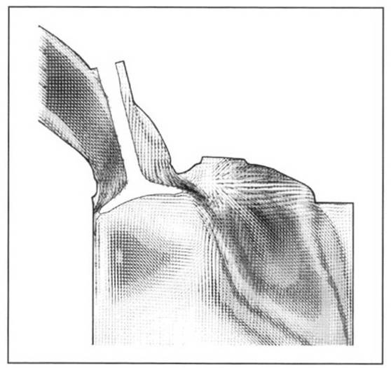
Fig. 7-78. Flow simulation at an intake valve
The design of the valve lifting lobes and the simulation of the valve train dynamics take a prime position in cylinder head development. The findings here have a direct impact on cylinder head design. Geometries such as the pushrod diameter, valve length, valve stem diameter, valve spring dimensions, and cam follower geometry are determined by these calculations. Imaging of the entire valve train in mechanical models also makes it possible to determine precisely the dynamic properties. The findings are reflected in the camshaft geometry and/or valve drive components.
A major contribution to designing the cylinder head coolant cavities is made by the three-dimensional flow simulation for the complete coolant circuit. This method is integrated into a larger calculation scheme that optimizes the entire cooling system, including the design of the water pump and the radiator. The geometry of the cylinder block and head cavities through which coolant flows is modeled and then compiled in a calculation matrix.
Figure 7-79 shows the section of the water jacket as an example of coolant flow simulation in a five-valve cylinder head with cross-flow cooling. The cylinder head receives the coolant through transfer bores in the cylinder head gasket. Their graduated diameters ensure nearly identical distribution of coolant to the various cylinders. About two-thirds of the coolant passes into the cylinder head at the exhaust valve side.
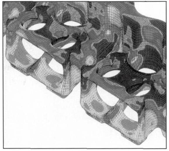
Fig. 7-79. Section of the water jacket for coolant flow simulation
The coolant flow passes across the top of the combustion chamber and past the exhaust ports to the spark plug well. Behind the spark plug the flow continues along a center coolant collector channel that runs longitudinally through the cylinder head. Presented in Fig. 7-79, as an example of the results of a simulation calculation, is the depiction of the convective heat transfer coefficients in the area around the exhaust port, which is subjected to severe thermal loading.
The dark areas correspond to a high thermal transfer coefficient, a result that is achieved by the optimized position and selection of the diameters for the transfer bores in the head gasket. By optimizing the cylinder head cooling pattern, with the support of simulation calculations, the temperature level at all the cylinders can be kept constant, with only minor deviations. This method makes a contribution to cylinder head development, which could be achieved using conventional techniques only with extensive effort in trials and testing.
Strength calculations represent a major area where technical calculations are used in engine development to determine the dimensioning and geometries of cylinder heads and their components. In order to make cylinder heads as light as possible and nonetheless sufficiently stiff, finite element calculations are carried out for the entire cylinder head.
The structural strength of the camshafts and their bearings can, for example, be examined for the design and position of the camshaft bearings. Wall thicknesses can be minimized by using strength analysis. Stiffening ribs are provided to increase structural strength. Thus, designs with a favorable effect on force flow can be predetermined in detail. A section from the FEM model for a complete cylinder head is shown in Fig. 7-80.
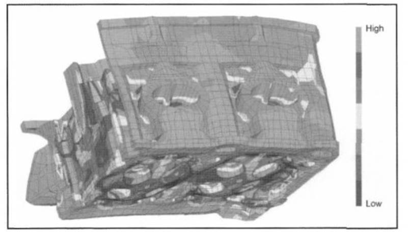
Fig. 7-80. Strength analysis at the cylinder head
The loading magnitudes for the calculation are the spring and mass forces of the valve train, the belt and chain forces at the end of the camshaft, and the forces applied by the cylinder head bolts. Shown in Fig. 7-80, after Mises, are the comparative stresses at the deformed cylinder head when subjected to thermal loading at nominal power.
Because of extreme demands for reliability and smooth running at the valve train, the design of the lobe contour assumes great importance. In addition to the purely kinematic design of cam contours, various computer programs are used to ensure good dynamic behavior in the valve train. To conduct the simulation calculations, the valve train structure is expressed as a multibody oscillating system with adjustable coupling conditions for friction, stiffness, damping, and degrees of freedom in movement.
The dynamic simulation for the entire valve train is obtained by calculating the design of individual valve systems to better evaluate the interactions of individual components with one another. The valve train is actuated by the lobe contour. Stiffness is determined on the basis of measurements made at the actual components or by using FEM calculations. The damping values are primarily experience values that are determined by comparing calculations and measurements.
The valve spring, as the main vibrating or oscillating element, is broken down into many oscillating subsystems. One goal in dynamic calculations is demonstrating rotation speed strength for the valve springs at the smallest possible valve spring forces, in order to keep overall valve train friction as low as possible. Simulation calculations make it possible to estimate even at a very early development stage the interactions among individual components.
Closely defined changes in component properties make it possible to influence the overall structure of the cylinder head and its components in such a way that the components’ own shape properties are manageable within the valve train’s excitation spectrum. Suitable tuning for the actuation itself, which is determined primarily by the cam contour, can also bring about a marked reduction in the dynamic effects at the valve train.
Oil circuit calculations can be conducted to fine-tune oil management in the cylinder head. Calculations for subsystems, such as for oil management at the cylinder head, make it possible, by simulating the entire motor oil supply system, to minimize the amount of oil required. This, in turn, keeps the amount of power consumed by the oil pump as low as possible. To do this, all the components in the engine in which oil is found are modeled in a virtual hydraulic system.
The objective is to optimize by simulating the oil using points in the cylinder head, such as the push rods, camshaft bearings, camshaft shifter, and oil spray nozzles. The calculation models are further refined, incorporating the results of basic experiments. These preliminary calculations make it possible to predetermine with considerable accuracy the cross sections for the oil passages; this reduces the number of costly trials that would otherwise have to be undertaken using the complete engine.
Date added: 2024-04-24; views: 723;