Balancing Single-Cylinder and Multicylinder Crank Gears
To be understood as mass balancing is the compensation of imbalances due to construction. The balancing of manufacturing-related imbalances is merely termed balancing.
Balancing Single-Cylinder Crank Gears. The rotating inertial force can be balanced by counter-mass(es) where the condition must be fulfilled that the static torque (product of the mass and distance from the rotary axis) of the rotating masses and the balancing mass(es) must correspond.

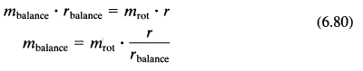
By dividing the balancing mass into two counter-weights, we obtain the following:
To keep the balancing mass small, it must be affixed at the greatest possible distance from the rotary axis (crankshaft axis); this is greatly limited by the constructive conditions. Basically, mass balancing should include a large static torque and a small moment of inertia.
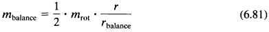
Oscillating inertial forces can also be compensated by revolving counter-masses since their force vector is com- posed of components in the direction of the cylinder axis (Y direction) and perpendicular to the cylinder axis (X direction). The balancing mass is selected so that the component in the direction of the cylinder axis corresponds to the oscillating inertial force; this is balanced, but at the price of a free component perpendicular to the cylinder axis (Fig. 6-43).
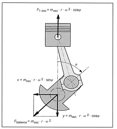
Fig. 6-43. Balance of oscillating forces using a revolving mass

Better conditions result when the oscillating first-order inertial force is not completely balanced. Since the crankcase along its height (Y direction) is more rigid than in the transverse direction (X direction), the oscillating first-order inertial force is not completely compensated so that the free X component does not become too large, and it is only 50% balanced. Completely balancing the rotating inertial force Frot and the 50% balance of the oscillating first-order inertial force is termed a normal balance—it was used even in the 19th century for drivetrains of steam locomotives. The mass balancing of designed passenger car engines is 50% to 60% of the oscillating inertial force and 80% to 100% of the rotating inertial force.

Another method for balancing oscillating inertial force is to use the so-called foot balance in which additional mass on the large connecting rod eye moves the conrod center of gravity toward the crank pin. The oscillating first-order inertial force is completely balanced when two balancing masses revolving in the opposite direction that are half the oscillating crank gear masses are symmetrically arranged in relation to the vertical engine axis. Then the two components in the direction of the cylinder axis compensate the oscillating inertial force; the two components perpendicular to the cylinder axis cancel each other out (Fig. 6-44).
Fig. 6-44. Complete balance of the inertial forces of the first order
To obtain a balance of the second order, the counter-mass must rotate at twice the crankshaft speed (Fig. 6-45).
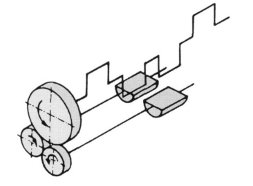
Fig. 6-45. Diagram of mass balancing of the second order in a four-stroke crank gear
Balancing Multicylinder Crank Gears. Automobile engines are built with multiple cylinders, i.e., with 3 to 12 (16) cylinders, as three-, four-, five-, and six-cylinder inline engines and V6, V8, and V12 (V16) engines, and as VR5 and VR6 engines. Earlier, there was also a V-4 engine (Ford 12 M). Recently, three-row engines (W-engines) with 12 cylinders have been developed.
These engines have three-, four-, five-, and six- (eight-) stroke crankshafts so that with a corresponding arrangement, the mass effects of the individual throws cancel each other out (self-balance). For this purpose, the throws are to be distributed evenly in the peripheral direction and
lengthwise direction:
- With centrally symmetrical shafts (equal to the throw spacing across the perimeter), the free forces cancel each other out.
- Centrally and longitudinally symmetrical arrangements of the throws of a four-stroke engine shaft have no free forces and torques of the first order; starting with six strokes, the shafts are completely force-free and torque-free. The criteria for the throw sequence are
- No or very low free mass effects. A simple rule of thumb for throw sequences with favorable mass balances was presented by O. Kraemer in Refs.
- Additional torque may not arise from mass balancing, and no additional inertial forces may arise from torque balancing.
- Even angular ignition spacing.
Free first-order inertial torque can be balanced by a shaft rotating in the opposite direction at the crankshaft speed with two countermasses of a corresponding size and lengthwise spacing (torque differential). The arrangement in the engine can be freely selected. Gears or chains provide the drive; frequently the oil pump drive is connected. To balance torque of the second order, the differential rotates at twice the crankshaft speed (Fig. 6-46).
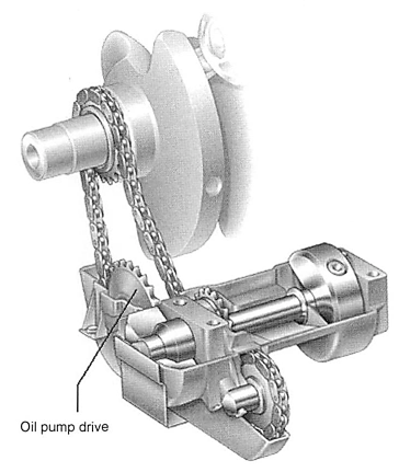
Fig. 6-46. Torque differential of the Audi V6
The following holds true for crankshafts of four stroke engines:
- Three-stroke shaft: free torque of the first and second orders occurs. The torque of the first order is compensated—especially in V-engines—with a torque differential.
- Four-stroke shaft: In four-cylinder, four-stroke inline engines, the inertial forces of second order are additive. These forces are balanced by two oppositely rotating shafts with countermasses (differential). Earlier, this was done only with tractor engines since the engine, the transmission, and rear axle housing form the bearing element of the vehicle.
Today, such differentials are also used for passenger car engines since beginning at 4000 min 1, the free second-order inertial forces are noticeable. The vertical accelerations are guided into the body and cause an "unpleasant humming."
Because of the high peripheral speeds of the bearing pin of this differential—up to 14 m/s—the bearing and drive must be carefully designed. The balance shafts are driven by a gear on a crankshaft web where the tooth face play of the drive must be harmonized to the shifts and rotational oscillations of the crankshaft (Figs. 6-47 and 6-48).
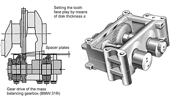
Fig. 6-47. Differential for inertial forces of the second order
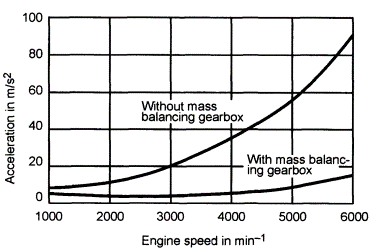
Fig. 6-48. Effect of the mass differential in a four-cylinder inline engine
By offsetting the height of the balance shafts, an additional oscillating torque of the second order can be generated that can also balance with gas force components of the oscillating torque. Since this is only slightly effective, it is not used (Fig. 6-49).
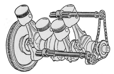
Fig. 6-49. Mass balancing of the second order with height-offset balance shafts (Mitsubishi)
- Five-stroke shaft: Free inertial torque arises, especially a large oscillating moment of inertia of the second order (see example). Passenger car and truck engines are built both with and without separate torque balance. In passenger car diesel engines, torque balance is not used, and the engine movement is captured by elastic bearings and shock absorbers. In five-cylinder truck engines, the torque differential is optional depending on the installation in the vehicle (engine systems with a flange-mounted gearbox and retarder, or busses because of the resonance behavior of the vehicle body).
- Six-stroke shaft: Centrally symmetrical and longitudinally symmetrical shafts (starting at six shafts) are balanced by themselves; they do not have any free mass effects.
The most important considerations in designing the mass balancing system are
- Complexity of assembly (differential)
- Operating behavior at high speed (second order): bearing, lubrication, etc.
- Increasing or decreasing the load on the crank gear bearing
- Balance of the gas force
- Rotational oscillation behavior
- Inertia
- Friction behavior
The free forces and torques of the different cylinder configurations are summarized in tables in the relevant literature. Mass balancing is used not only on the crankshaft drive but also on the valve gear, i.e., camshafts:
- The body is drilled eccentrically so that the manufactured imbalance can largely compensate for the free valve mass forces.
- Balancing masses are placed directly on the camshaft (Fig. 6-50).

Fig. 6-50. Camshaft with balancing mass
Date added: 2022-12-29; views: 859;