Indirect Drive Valve Trains
Included in this group of valve trains are
- Cam follower valve trains with stationary valve play compensation elements; the cam follower rests on the spherical upper end of the hydraulic element.
- Rocker arms that pivot on a shaft.
- OHV concepts comprising the cam follower (flat or roller valve lifter), pushrods, and rocker arms.
There is a clear trend in cam follower drive trains toward cam followers that are made of sheet metal and are fitted with a rolling bearing at the point of contact with the camshaft. Cam followers made from cast steel in a precision-casting process give the engineer greater design leeway (stiffness, moment of inertia). The cost advantages for the sheet metal cam are so great, however, that precision cast cam followers are used only in exceptional cases (Fig. 7-112).
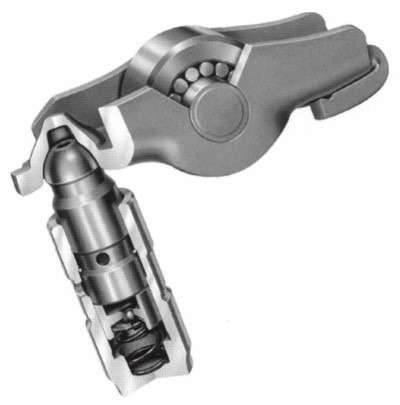
Fig. 7-112. Roller cam followers with hydraulic element
When compared with plain cam followers or valve trains with valve lifters, the use of the rolling bearing effects a reduction in friction, particularly in the lower speed range that is so relevant to reducing fuel consumption. This reduction in friction losses is, however, paid for with a significant reduction in damping of torsional vibrations at the camshaft, which has consequences for the timing chain or belt.
Moments of inertia and stiffness are highly dependent on the shape of the lever. Short levers cause low moments of inertia, with masses on the valve side that are lower than for valve lifters. Seen as a whole, roller cam followers are inferior to valve lifters in regard to stiffness.
The profiles for the lobes in valve trains incorporating roller cam followers differ significantly from those in valve trains that use valve lifters (greater radius at the apex, shorter lobe stroke—depending on the lever ratio, and concave flanks). In order to keep the concavities of the cam narrow enough that they can still be ground with mass production technology, preference is given to valve train geometries in which the roller is positioned approximately at the center between the valve and the hydraulic element. Here the camshaft is located above the roller.
This arrangement makes it possible to keep the hazard of “pumping up” under control (see hydraulic valve play compensation).
This configuration, with the cam lobe offset from the valve stem centerline, makes the cam follower concept interesting for four-valve, direct-injection diesel engines since in these units the valve stems either are parallel or have only a very small included angle (Fig. 7-113). Only with the use of cam followers is there sufficient clearance between the camshafts. Using cam followers also makes it possible to serve “inverted” valve arrangements (e.g., DCC OM 668).
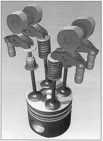
Fig. 7-113. Valve train for a direct-injection diesel engine with cam followers
As opposed to cam followers, rocker arms are mounted on shafts. One differentiates between rocker arms in which the pivot point is toward the center of the lever (Fig. 7-114) and those that pivot at one end; the latter are also known as cam followers.
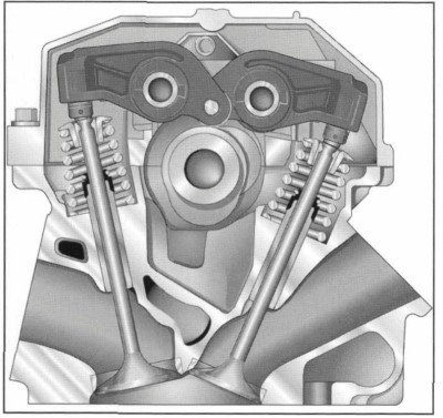
Fig. 7-114. Typical rocker lever valve train
The camshaft is located below one end of the rocker arm while cam motion is transferred via either a plain, sliding surface or a cam roller. To achieve low friction losses, needle-bearing cam rollers are used in most modem rocker arms. The valve is lifted at the opposite end of the lever, via a hydraulic valve play compensating element or a setting screw used for mechanical valve play adjustment (Fig. 7-115).

Fig. 7-115. Side view and section through an aluminum rocker arm
The contact surface at the rocker arm has to be angled to maintain unbroken contact between the adjustment element and the end of the valve stem as the arm executes its rocking motion. Since neither the hydraulic compensation element nor the mechanical adjustment screw is mounted in the rocker arm to specify a direction, the contact surface at the valve actuation element is crowned.
This geometric design leads to relatively high surface pressures at the end of the valve stem. Where surface pressures are excessive, hydraulic elements are employed, which incorporate a pivoted foot at the point of contact with the valve. The contact itself is at a virtually flat surface, while the pivoted foot executes a movement around a ball mounted on the hydraulic element (Fig. 7-116).
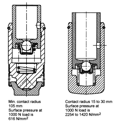
Fig. 7-116. Hydraulic elements for rocker arms, 11 mm O.D.
Aluminum, preferably manufactured in a die-casting process, or steel is used here.
Oil is supplied to the hydraulic compensator elements from the rocker arm shaft. From this point, bores in the rocker arm lead to the hydraulic elements. Support shims with a little play in the guide, which are always used in aluminum rocker arms, permit the escape of air that, for instance, can get into the hydraulic element when the engine is started. Either shims such as this or very tiny bores are used to vent steel rocker arms.
Starting at the oil supply bores in the rocker arm shaft, bores in the rocker arm can be used to spray the cam roller or the cam sliding surface.
Rocker arms of this shape and design are found in diesel and gasoline engines. Using rocker arms makes it possible to set up two-, three-, or four-valve arrangements with just a single camshaft. Where valve trains with two intake or exhaust valves are used, double or twin rocker arms can be used to lift two valves simultaneously with a single cam. Valve play is compensated individually, however, with the aid of hydraulic elements.
It is even possible to actuate three valves (Fig. 7-117). Audi uses a triple cam follower in the valve train for its V-8 engines incorporating three intake valves. Actuation force flows from two cam lobes to two rollers in the rocker arm and then to three hydraulic compensators.
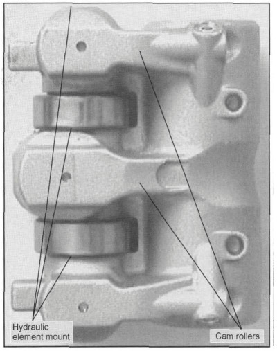
Fig. 7-117. Triple cam follower for the Audi V-8 engine
In addition to the solutions previously mentioned, where the rocker arm actuates the valve directly, there are also rocker-arm valve trains that use bridges, either guided on posts or free-moving, to lift two valves simultaneously. In four-valve diesel engines, including those with an inverted valve arrangement, it is possible to actuate all the valves with just a single camshaft while at the same time maintaining the space needed for the injection nozzles.
Stiffness values in rocker arms are low, because of the geometry and, particularly, the great distance between the cam contact point and valve contact point, the relatively large number of contact points and the shaft, which have to be taken into account, in addition. The much more direct force flow in cam follower designs produces far better stiffness values.
Date added: 2024-05-02; views: 828;