Future Trends. Cylinder Shutdown
Variable Valve Drive Trains with Single-Step and Multistep Variability. Building upon the systems explained in Section 7.10.1.1, it is possible to respond to the needs of engine designers and the desire of thermodynamics engineers to apply differing lift curves, selectively, to an engine valve. This is done by introducing a shifting capability into the transmission path for the valve train.
Valve lift cutout and switching systems using defeat- able force transmission elements such as rocker arms, cam followers, and valve lifters have already been implemented in small production runs (Fig. 7-118). A separate cam has to be provided to initiate the stroke for each additional and alternate valve stroke length—unless the alternate stroke is no lift at all.
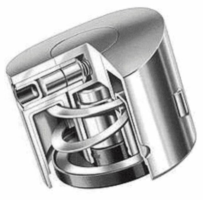
Fig. 7-118. Switchable valve lifter
When valves are simply disengaged (to shut down specific cylinders, for example), it is then possible to do without a second cam for each cam follower.
Here the element that follows the cam lobe is decoupled from the engine valve. This “lost” motion lends its name to what is sometimes called a “lost motion” stroke; the negative mass forces here have to be absorbed by a lost motion spring, since the valve spring is no longer actuated. The section of the valve train for which no valve cutout or cylinder shutdown is planned then executes the stroke motion without any effect on valve stroke length.
In the case of defeatable cam follower units, which may also be fitted with hydraulic elements, this lost motion can be absorbed in supporting elements (Fig. 7-119); alternately a compression spring between two sections of the lever absorbs the mass forces for the part of the lever that continues to be moved (Fig. 7-120).

Fig. 7-119. Switchable support element
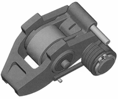
Fig. 7-120. Switchable cam follower
The situation is similar for cam follower and rocker arm valve trains. Here the separation of the physical connection in the lever (or lever system) and/or in the switching mechanism is the normal configuration since, because the levers are borne on shafts, decoupling at the support presents difficult engineering problems (Fig. 7-121).
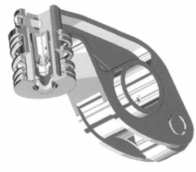
Fig. 7-121. Switchable rocker arm
In OHV valve trains, used primarily in older types of large-displacement engines, shutting down the valves is simple. Here it makes sense to interrupt the physical connection at a point near the cam—such as at the (roller-type) push rod—to keep the masses in a motion as small as possible when in the deactivated state.
The switchable, roller- type push rod shown in Fig. 7-122 is designed for cutout operation and as a consequence is fitted with only one rolling bearing to follow the cam contour. This has such a great effect on the engineering design that it differs severely from the switchable valve lifter shown in Fig. 7-118 even though the two units are similar in function.
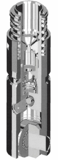
Fig. 7-122. Switchable OHV valve train
The latter, with two cam contact surfaces (sliding surfaces in this case) and operating in conjunction with a cam packet, can also be employed as a true selector between two differing valve stroke curves. This stroke selector is used to activate different valve lift curves, the choice depending on the momentary operating situation.
In addition to the two-stage concepts, multistage concepts have also been implemented (Fig. 7-123); they approach valve trains with stepless, fully variable lift stroke. The fully variable valve drives, engineered without a throttle if at all possible, involve considerably greater space requirements and considerable complexity in both engineering and control technology.
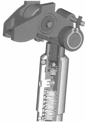
Fig. 7-123. Switchable support element and switchable cam follower
Consequently, one could well conceive of systems that use cam stroke selectors with separate changeover for the individual valves in multivalve engines in order to achieve a multi step effect with less effort than that required for fully variable systems.
Enhanced variability, particularly in regard to the intake valve actuation train, can be achieved with less effort in combination with camshaft adjustment or shifting systems. Here the results achieved by optimizing intake valve lift (as dictated by the operating situation) by varying the lift cycle and by shifting phases do, in fact, approach the fully variable valve train while at the same time utilizing familiar, rugged components (Fig. 7-124).

Fig. 7-124. Porsche VarioCam Plus System
The coupling mechanism can be actuated either hydraulically or mechanically. Examples of mechanical actuation elements are linear and rotational electromagnets that activate the coupling and lockout mechanism via a physical connection. A hydraulic control concept (Fig. 7-125) uses the oil circuit already on hand in the cylinder head.

Fig. 7-125. Coupling mechanism (switching positions)
The assignment of the switching states (coupled/decoupled) is made here with changes in oil pressure. Here the engineering implementation of both potential versions (coupling at zero pressure or decoupling at zero pressure) has been successful, and this broadens freedom in thermodynamic design.
The mechanical switching period that takes into account the coupling element excursion only may be in the range of about 10 to 20 msec where peripheral conditions are good. Since the other influences such as electrical and hydraulic dead times can be largely eliminated by the engine electronics, it becomes clear that switching from one operational status to the next is possible within a single camshaft revolution, up to high rotation speeds.
Cylinder Shutdown. A method for implementing one of the variabilities described above is cylinder shutdown, which is used primarily in large-displacement engines (with 8, 10, or 12 cylinders, for example). The purpose of cylinder shutdown is to minimize the gas exchange losses (pumping and throttle losses, Fig. 7-126) and/or to shift the operating point.

Fig. 7-126. Gas charge change (p-v chart) with/without cylinder shutdown
Reduction of friction loss is achieved with lower spring forces at the deactivated cylinders. Here the camshaft works only against the lost-motion spring forces that are less than comparable valve spring forces, by a factor of 4 to 5. Equidistant ignition sequences make it possible to “convert” standard V-8 and V-12 engines to V-4 or six-cylinder inline engines, respectively. Trials carried out using a V-8 engine at a test bed showed that employing cylinder shutdown made it possible to achieve fuel savings potentials of from 8% to 15% in normal driving cycles.
Stroke Changeover. A second way to implement variability in the valve stroke is to change the length of the valve lifting stroke. This concept aims to increase thermodynamic efficiency particularly by reducing the losses associated with the gas charge change.
Positive effects are also expected here in regard to friction losses since the lost-motion springs used here are also relatively weak; thus the total effective valve spring and lost-motion spring forces in partial stroke operations are less than the valve spring forces effective in full stroke operation. Implementing this system together with camshaft shifting lets us achieve thermodynamic optimization at many of the engine’s operating points, and this will be reflected in a significant drop in fuel consumption.
This technology has achieved full maturity for volume production in the new Porsche 911 Turbo. Because of the four-valve technology widely used today, this system can achieve a multistep effect that represents a great advance toward full variability (Figs. 7-127 and 7-128).
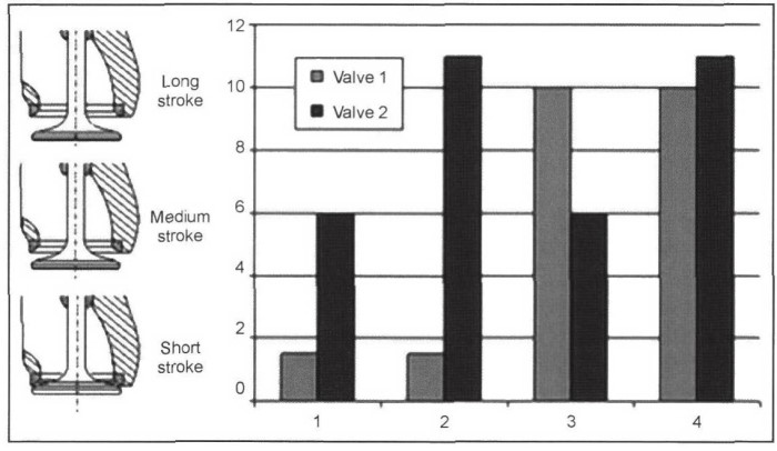
Fig. 7-127. Multistep

Fig. 7-128. Porsche 911 Turbo engine map
Fully Variable Valve Trains. Among the fully mature embodiments of fully variable valve trains is the BMW Valvetronic concept. It offers great benefits in terms of consumption as well as in retaining stoichiometric operation with all its advantages and, in addition, can be used all around the world, regardless of fuel formulations (sulfur content).
The Valvetronic achieves engine operation without the need for a butterfly throttle valve. Cylinder fill at partial load is regulated by the intake valve lifting stroke and opening period. The intake and exhaust camshafts are driven by variable cam adjustment.
To achieve stepless adjustment of intake valve stroke, an intermediate lever, backed against an eccentric shaft, is inserted between the camshaft and the cam follower. The contour of the contact surface between this intermediate lever and the roller cam follower defines the valve lifting curve. Rotating the eccentric shaft moves the fulcrum for the intermediate lever and thus—steplessly—changes the lever ratio and, consequently, the relationship between the cam lobe stroke and the valve stroke. In this way, it is possible to achieve valve excursion from about 0.3 mm at idle to 9.7 mm at full throttle.
Date added: 2024-05-02; views: 908;