Chain Tensioning and Guide Systems
Introduction. In addition to the synchronous belt tensioning and deflection systems described in Section 7.10.2, timing chains have long been used to drive camshafts in internal combustion engines. In addition, they are found in conjunction with the balancer shaft drives more frequently and as the power connection between the crankshaft and the oil pump. Chain tensioning and compensation for chain wear are normally affected with a chain tensioning element; any of a number of systems may be chosen, depending on the installation location.
In contrast to belt drives, the use of free span lengths in chain drives is very limited so that the tensioning and guide rails used to guide the chain attain great significance. Some of the fundamentals for the individual components are to be discussed in greater detail below. The terms used here are explained in Fig. 7-133 on the basis of a DOHC timing drive configuration.

Fig. 7-133. DOHC timing scheme to explain the nomenclature
Chain Tensioning Element. Hydraulic chain tensioning equipment is used in most of the timing chain drives found on the market today. They are, as shown, situated at the slack span of the chain drive and are connected with the motor oil circuit by supply bores.
They must satisfy the following main requirements:
- Preloading the chain drive to keep the chain from “climbing” or jumping on the sprockets
- Compensating for the chain wear occurring during the engine’s service life
- Damping the oscillations induced by the chain at the tensioning rail
- Reducing tooth jump, particularly in chains stretched as a consequence of wear
In some cases the tensioning devices, into which oil spray nozzles are integrated, also handle the lubrication function needed to ensure proper chain drive functioning.
Figure 7-134 provides a schematic depiction of a tensioning element when installed.

Fig. 7-134. Leakage gap tensioning element with integrated retraction stop
This is a speed-proportional, leakage-gap damping unit that, because of the inclusion of the check valve, exhibits directional (single-sided) damping. The motor oil passes initially through the supply bore and a system of grooves in the tensioning element and into the reserve chamber. If, when the load is relieved on the slack span, excess pressure is created in the high-pressure chamber (located between the plunger and the housing) because of the spring-induced extension of the tensioning plunger, then the check valve is opened and oil passes from the reserve chamber into the high-pressure chamber.
When a load is placed on the plunger, the valve spring and the pressure building up in the high-pressure chamber close the check valve. Oil is forced through the leakage gap and out of the high-pressure chamber. Thus, a damping effect is created, the amount being a factor of the width of the gap between the plunger and the housing. The pressure prevailing in the high-pressure chamber during the damping process can be as much as 80 bar and even more in isolated cases.
Because of the sensitivity of the damping characteristics to the size of the leakage gap, manufacturing precision in the individual components has a major influence on tensioner quality.
Some of the tensioner versions that have been engineered incorporate retraction stops to keep the tensioner from collapsing when the load is reversed at engine standstill. This effectively prevents tooth jump when the engine is restarted.
When designing the tensioner components, particular attention is paid to those segments of the excursion stroke that are active while the engine is running. This is shown schematically in Fig. 7-135. The portion of the stroke that compensates for thermal expansion has to be determined carefully, taking account of the materials used in building the engine. If this portion is underdimensioned, then there is a hazard that the tensioner will bottom out and, as a consequence, the chain will be overtightened.
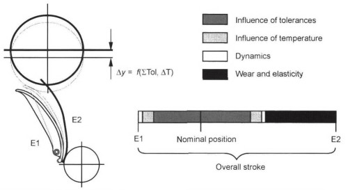
Fig. 7-135. Subdivision of chain tightener stroke
Simple tensioners are used, especially in oil pump drives, because it is often possible to do without closely defined damping. In some cases plastic elements are even chosen instead of the steel components normally employed.
Tensioning and Guide Rails. Tensioning and guide rails are used to guide the chain along the spans. They normally consist of a slip-promoting plastic surface and a backing element adapted to suit the geometry of the space in which it is installed. Backing elements made of die-cast aluminum are superseded more and more today by injection-molded plastic parts. Glass reinforcing fibers may be added to the injection resin for the backing unit in order to stiffen the relatively soft plastic, which is also highly sensitive to heat.
Design work here often uses finite element calculations to determine the loading that will be encountered. Figure 7-136 shows a tensioning rail manufactured completely from nonreinforced plastic that incorporates metal reinforcement only in the area around the pivot point.

Fig. 7-136. Tensioning rail made of solid plastic
Sprockets. Sprockets are used to transmit chain forces to the various shafts in the engine. The tooth geometry for these sprockets follows applicable standards without, however, making full use of the tolerances allowed there. Either precision stamped or sintered components are employed, depending on the sprocket geometry. In isolated cases, and particularly where multiweb chain is used, these sprockets may be manufactured so as to induce internal stresses.
Date added: 2024-05-02; views: 966;