Embodiments. Valve Head. Valve Seat
Valve Head. The theoretical diameter of the valve seat is the basis for the engineering design of the valve.
Overall disk height depends upon the combustion pressure and the average valve component temperature. This height is established by finite element analysis. Practice has shown that values of from 7% to 10% of valve head diameter are common.
The thickness of the edge of the disk determines the stiffness of the valve head and is coordinated with the valve seat angle; at 45° it is about 50% of overall disk height, at 30° approximately 55% to 60% of overall disk height.
The valve seat angle is generally 45°. Seat angles of 30° and 20° may, however, also be selected to reduce valve seat wear. Small seat angles are indispensable in gas-fired engines. Manufacturing technology requires a difference of at least 5° between the valve seat angle and the valve face angle, Fig. 7-142.

Fig. 7-142. Differential angle and valve seat width
The differential angle between the valve seat and the seating ring achieves initial sealing along a line of contact, thus creating better seal of the face against the combustion chamber. Attention is needed to ensure that the valve seat width is greater than the seating ring contact width.
Curved depressions on the valve face are provided to reduce valve weight, to influence combustion chamber shape, and to distinguish between intake and outlet valves or similar valves.
The ideal shape for the transition from the concave area at the back of the head to the valve stem can be identified only with the appropriate engine trials.
Valve Seat. The seat for the exhaust valve is heavily impacted by heat and corrosion, which is why, as a rule, it is hardfaced with special alloys. In isolated cases, this is also done for the intake valve even though here martensitic hardening is normally used because of the material selected. Hard- facing can be used to reduce wear and enhance the sealing effect.
The following processes are used for valve hardfacing:
- Fusion welding, in which the hardfacing material in rod form is melted and applied by means of an oxy- acetylene flame.
- Electrical PTA process (plasma-transferred arc) in which the pulverized hardfacing material is melted in a plasma arc and applied to the workpiece.
These hardfacing techniques are used for hollow valves, bimetallic valves, and occasionally for monometallic valves, as well. To keep any reduction in hardness at the inductively hardened valve seat within acceptable limits, it is necessary to ensure that valve temperatures do not exceed a maximum of from 550 to 600°C.
Valve Stem. This component is used to guide the valve inside the valve guide and is defined by the first keeper slot provided to mate with the conical keeper and by the sweeping shoulder and/or the transition to the concave area at the back of the head.
To limit the formation of soot on the end toward the gas port, a sweeping shoulder is made by narrowing the stem diameter, Fig. 7-143. When the valve is closed, this shoulder should be inside the valve guide by about one-half of the valve lifting stroke.
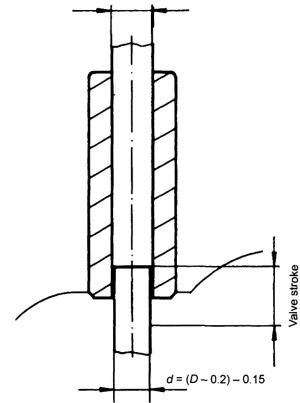
Fig. 7-143. Valve stem with narrowing and sweeping shoulder
If, during the valve closing phase, bending is induced because of cylinder head warping or noncongruence of the centerlines, then it is desirable for the welding seam to be inside the valve guide. This is why the friction welding seam for bimetallic valves is moved to at least one-half stroke length inside the valve guide.
Depending on the tribologic situation, it is necessary to protect the valve stem surface against wear by using chrome plating or nitriding. There is a specific ratio between valve stem diameter and the valve disk diameter. The disk-to-stem ratio for intake valves is 6:1; for exhaust valves it is 5.5:1.
As a rule, the valve stem is cylindrical in shape. To take account of the variations in expansion due to the temperature gradation the valve stem may be tapered between 10 and 15 μm, depending on the length and diameter of the stem.
Valve stem ends featuring multiple keeper slots, the purpose of which is to support unrestricted valve rotation, is always inductively hardened in the area where the keeper makes contact in order to avoid wear. It is for the same reason that, where the valve actuators exert very high surface pressures, shims made of tungsten carbide or a hardenable stem material are welded into the end of the shaft, Fig. 7-144. Valves with a single keeper slot are seldom hardened, but here, too, shaft end shims made of tungsten carbide or other materials that can be hardened may be used for wear protection.

Fig. 7-144. Types of keeper slots in valve stems
The distance between the end of the stem and the middle of the keeper slot may not exceed 2.5 mm. The sharp edges at the end of the stem are smoothed either by chamfering at less than 45° or 30° or by rounding, which assists in automatic valve installation.
Valve Guide. The valve guide ensures that the valve centers in the valve seat and that heat can be dissipated from the valve head, through the valve stem and to the cylinder head. This necessitates an ideal clearance valve between the guide bore and the valve stem. If there is insufficient clearance, then the valve tends to stick. Too much clearance interferes with heat dissipation. One should strive to achieve the smallest possible valve guide clearance.
In addition, it is necessary to ensure that the end of the valve guide does not protrude unprotected into the exhaust port as otherwise there is a danger of the valve guide dilating and combustion residues entering the valve guide. As a rule of thumb, the length of the valve guide should be at least 40% of the length of the valve.
To ensure perfect valve functioning, it is necessary that the offset between the centerlines of the valve shaft and the seating ring be kept within certain limits (0.02 to 0.03 mm in a new engine). Excessive misalignment can cause above all serious bending of the valve disk in relationship to the stem. This excessive loading can lead to premature failure; other consequences may also be leaks, poor heat transmission, and high oil consumption.
Date added: 2024-05-02; views: 914;