Valves. Functions and Explanation of Terms and Concepts
Functions and Explanation of Terms and Concepts. Intake and exhaust valves are precision engine components used to block gas flow ports and to control the exchange of gases in internal combustion engines. They are intended to seal the working space inside the cylinder against the manifolds. An example of a valve in place in the engine is shown in Fig. 7-137.
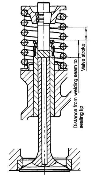
Fig. 7-137. Hollow valve in place in the engine
The intake valves, which are not subjected to such extreme thermal loading, are cooled by incoming gases, by thermal transmission at the seat, and by other means. Exhaust valves, by contrast, are exposed to severe thermal loads and chemical corrosion.
These two types of valves are manufactured using different materials, matched to the functions they perform. It may be assumed that during an engine’s service life the valves will execute about 300 million operating cycles, many at very high temperatures. The most important terms used to describe valves are depicted in Fig. 7-138.
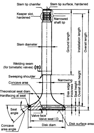
Fig. 7-138. Terminology used for valves
Types of Valves and Manufacturing Techniques. Valves may be subdivided essentially into three major groups: Monometallic valves, bimetallic valves, and hollow valves.
Monometallic Valves. Monometallic valves may be manufactured either in the hot extrusion process or by upsetting.
The starting point in the hot extrusion process is a section of rod whose diameter is about two-thirds of the final disk diameter; its length corresponds to the volume of the blank to be manufactured. This rod is heated and reformed to make the blank in two forging steps.
During the upsetting process a ground section of rod, the diameter of which is slightly greater than the ultimate valve stem diameter, is first heated at the end; the rod is then forced forward to form a “pear,” which is then reformed in a die to create the valve head.
Bimetallic Valves. Bimetallic valves permit the ideal combination of materials, each matched exactly to the needs of the valve stem and the valve head. Here again one works on the basis of a heat re-formed head that is made in the process described above and then attached to the stem by friction welding, Fig. 7-139.
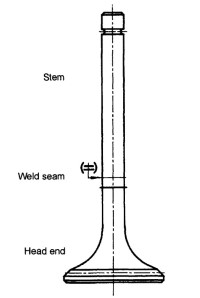
Fig. 7-139. Bimetallic valve
The pairs of materials normally given preference are X53CrMnNiN219, X50CrMnNiNb219, X60CrMnMoV- NbN2110, and NiCr20TiAl for the head and X45CrSi93 for the stem.
It makes good sense to position the welding seam at a point along the valve stem so that, when the valve is closed, the seam is inside the guide by half of the valve lifting stroke and/or about 6 mm above the sweeping shoulder. Here, for reasons dictated by the manufacturing technology, it is necessary to ensure that the length of the cylindrical section on the head itself is at least 1.5 times the stem diameter. The seats for bimetallic valves can, of course, also be hardfaced.
Hollow Valve. This version is used primarily for the exhaust valves and, in certain special circumstances, on the intake side as well, to lower the temperatures primarily in the concave area at the back of the head and at the disk area and for weight reduction.
The sodium used for heat transmission is located in the hollow cavity in the valve stem and can move freely. A portion of the heat impinging on the concave area at the back of the head and the valve face is passed by the liquid sodium to the valve guide and, from there, to the coolant circuit, Fig. 7-140.
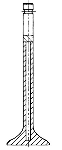
Fig. 7-140. Hollow valve
If one employs hollow valves to reduce temperatures, then about 60% of the volume inside the hollow space will be filled with metallic sodium. This liquid sodium (melting point 97.5°C) is shaken inside the valve cavity to an extent corresponding to the engine speed. It transports heat from the valve head into the valve stem. The degree of temperature reduction at perfect thermal energy flow and the smallest possible working clearances are in a range of from 80 to 150°C.
Hollow valve variants:
- “Tube on solid metal” version: The head, which is drilled from the stem end (forming the tube), is attached by friction welding to a (solid) stem end section, which is alloyed so it can be hardened.
- “Closed-off” version: This version is far more elaborate in its manufacture than the version described above. The workpiece is also drilled from the stem end. The bore is closed with inductive heating and subsequent forging. The stem end section is attached with friction welding. Such closed-off hollow-stem valves are used primarily in high-performance engines and aviation applications.
- Hollow valve: This valve represents a further measure taken to reduce weight and enhance heat transfer away from the center of the valve disk. These valves, in contrast to the above-mentioned designs, are drilled and machined from the disk end. The opening is closed by inserting a capping plate, using a special process to do so. These valves, more expensive to manufacture, are used primarily in racing engines, Fig. 7-141.
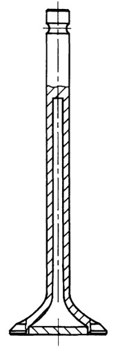
Fig. 7-141. Hollow valve
Hollow valves may be made at stem diameters of 5 mm and upwards. The diameter of the internal bore is about 60% of the stem diameter.
To avoid exposing the valve stem seals to excess temperatures, the bore inside the valve has to end about 10 mm away from the contact range for the sealing lip. Any change in clearance between the valve stem and the valve guide, different from that found in solid valves, is also observed. Valve sticking is reduced by tapering the stems slightly to compensate for the temperature gradient.
Hollow valves may be of a single metal, but bimetallic valves with the following combinations of materials are more common: X53CrMnNiN219, X50CrMnNi- Nb219, and NiCr20TiAl for the head section and X45- CrSi93 for the stem section.
Date added: 2024-05-02; views: 889;