Exhaust Manifold
Economical cast manifolds were the standard in vehicle engineering for many years. Only in sportier vehicles—in the interest of optimizing torque and performance—were single-walled tube-runner manifolds used. They enabled individualized runner lengths, diameters, configurations, and mounting. Combustion at full throttle was largely substoichiometric so that the exhaust temperatures were relatively low.
In the mid-1980s legislators in Europe imposed pollutant emission limits, making it necessary to equip the vehicles with catalytic converters. As emission laws became more stringent, exhaust pollutants following a cold start had to be reduced further and more quickly.
One of the options for rapid reduction was found by reducing the exhaust manifold’s thermal mass (or capacitance). In the cast iron version the mass for a four- cylinder manifold, at from 4 to 8 kg, is quite high. If the exhaust manifold’s thermal mass is low, then the heat in the exhaust can bring the catalytic converter up to the so-called light-off temperature more quickly.
The light-off temperature is defined as the exhaust temperature at which half of the pollutants are converted. Options for reducing the mass are presented in Sections 7.23.2 to 7.23.4. Figure 7-333 shows the influence of manifold design on the temperature ahead of the catalytic converter when using a standardized test cycle.
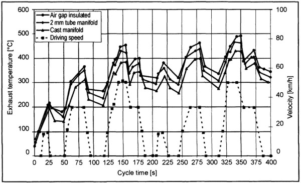
Fig. 7-333. Influence of manifold design on temperature ahead of the catalytic converter
A further aspect that has had a negative effect on traditional exhaust gas manifold design is the increase in exhaust temperatures, resulting from the increase in the power density and operating with a stoichiometric fuel-air mix across wide areas of the engine map. Whereas in the early 1980s we found exhaust temperatures of 850°C in gasoline engines and 650°C in diesel engines, these levels today have risen to beyond 1000°C in gasoline engines and as much as 850°C in diesel models.
Especially in gasoline engines, this fact has a significant influence on the selection of the casting material. Earlier cast manifolds using silicon-molybdenum (SiMo) alloys reached their application limits at exhaust temperatures of up to 900°C. Higher-quality gray casting qualities containing 20% to 36% nickel can be used up to about 1000°C. To handle even higher exhaust temperatures, it is necessary to resort to nickel- or cobalt-based alloys like those that are also used in turbine engineering.
Cast manifolds, because of the typical wall thickness of from 4 to 6 mm (tube manifolds, by comparison, are 1.0 to 1.8 mm thick), generally operate in a temperature range that could have a negative effect on durability through time. The changes in microstructure occurring at these temperatures and the inadequate thermal strength result in plastic deformation.
During the cooldown phase microfissures appear, and these lead to manifold failure in the long run. Neither have extensive studies on the development of new manifold casting materials resulted in a sufficiently improved service life. One solution is to assemble the manifold from steel sheet or steel tube components. This design is considered to be durable. Thus, there are examples in which cast SiMo manifolds were tested over 250 hours, while assembled manifolds for the same engine were tested under identical conditions for up to 500 hours.
For maximum exhaust temperatures, diesel engines offer a better operating environment for cast materials. In response to new legislation, however, there are trends toward replacing—in diesel engines, as well—cast components with those made of sheet metal.
Further arguments in favor of substituting sheet material for castings are efforts to reduce overall vehicle weight and ultimately to also reduce the great tendency for a cast manifold to heat up after the engine is shut down (Fig. 7-334).
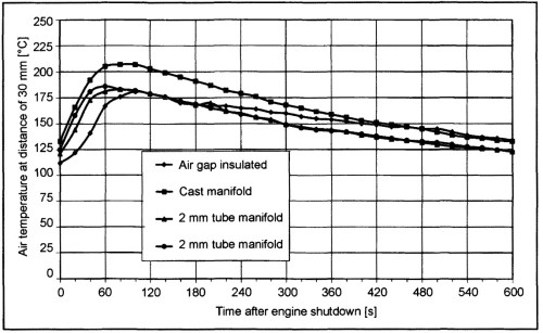
Fig. 7-334. Soaking behavior for various manifold designs
The installation situation permits a very compact design using cast manifolds while sheet metal manifolds tend to take up more space, because of optimized runner lengths and minimum bending radii that have to be observed.
When the various manifold designs are heated and cooled, we find that cast materials, in comparison to tubing and sheet metal, involve a high degree of thermal lag. An assembled design with air gap insulation lies between casting and tubing in regard to this factor.
The need for heat shielding is determined primarily by the component’s surface temperature, the postheating properties, and the proximity of nearby components. Since the energy transmitted in irradiated area rises with the fourth power of the surface temperature, it makes good sense to shield cast and tube manifolds that can reach surface temperatures of up to 800°C.
One very good alternative is double-walled or jacketed manifold incorporating an air insulating air (AGI); here the tubing carrying the exhaust gas is separated from the supporting structure by an air gap. These manifolds, which, by their very nature, incorporate their own heat shield and exhibit maximum surface temperatures of from 450 to 500°C, generally do not require any additional shielding.
Date added: 2024-07-30; views: 600;