Lubrication System. Components and Function
Lubrication. Lubrication is the coating or wetting of sliding partners with a lubricant; this can be “liquids, gases, vapors, i.e. fluids, plastic substances and solids in powder form.” Functions of the lubrication are
- Power transmission.
- Reduction of friction and wear.
- Precision sealing: Parts sliding on and inside one another can, in principle, be sealed purely by means of a lubricant film.
- Damping of impact and vibration.
- Reduction of noise.
- Cooling: Dissipation of friction heat.
- Cleaning: Discharge of particles of all kinds.
- Corrosion protection.
The lubricant is a machine element; in the bearings it transmits the component forces by lubricant films with thicknesses of just a few thousandths of a millimeter. This ability is derived from the viscosity, i.e., the ability of the lubricant to resist a change in shape.
The individual fluid particles rub together; tangential stresses (shear stresses) are created at their contact surfaces. The magnitude of these stresses is dependent on the shear rate perpendicular to the flow direction dv/dz and a material characteristic of the fluid, its kinematic viscosity η (viscousness) (Newton’s shear stress). The kinematic viscosity, in turn, depends on the lubricant, its temperature, and pressure, as well as on the shear rate (Fig. 8-3).
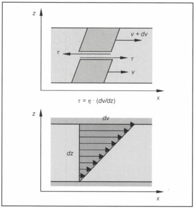
Fig. 8-3. Shear and shear rate
The shear stresses perform friction work (dissipation work) in sliding direction; this kinetic energy that is transformed into heat is “lost.” In machine operation, the fluid friction has a disadvantageous effect: It costs mechanical energy and heats up the lubricant; that, in turn, reduces the load-bearing strength of the lubricant film.
This heat of friction has to be dissipated, hence, necessitating additional design and operational measures. In the worst case, with mixed friction, it leads to wear of the sliding partners right up to seizure. But without inner friction, a fluid could not transmit forces.
Components and Function. A lubrication system consists of lubricant-conveying pipes, pumps, filters, heat transmitters, and the control elements in their arrangement relative to one another. Of particular note are the oil reservoir (oil sump), oil pump(s), oil heat exchangers, oil filters, control valves, filler neck, and the monitoring of the oil volume (oil level) and oil volumetric flow (oil pressure).
A distinction is made for the following:
- Fresh oil or total-loss lubrication: Here the oil is pumped from an oil reservoir to the individual consumers. It has to be ensured that clean, cool oil is delivered to the consumers at all times. With careful metering the oil consumption can be kept low. The fresh oil lubrication method is used in two-stroke SI engines with fuel injection.
- Mixture lubrication: This method of lubrication is used today predominantly for small two-stroke engines. The lubricating oil is added to the gasoline in a particular ratio (1:50 or 1:100) during refueling. The oil enters the cylinder together with the fuel on the intake stroke and into the crank chamber with the overflow. The discharged oil lubricates the bearings and the cylinder wall. Lubricating oil also enters the exhaust with the scavenging air, which increases the oil consumption and reduces the exhaust gas quality.
- Forced-feed lubrication: Four-stroke engines and two- stroke diesel engines are generally lubricated by this method. A pump delivers the oil from a tank via a system of pipes to the consumers, and from there it flows back pressure-free to the tank.
- Dry sump lubrication: Dry sump lubrication is used for conserving space (installation space) or for special operating conditions (off-road vehicles, sports cars). A suction pump draws the oil into a separate tank, and from there it is returned by a pressure pump to the oil system after cooling and filtration. The suction and pressure stages of the pump are often designed together.
Engine lubricating oil circuit: The intake screen of the oil pump is located at the lowest point of the oil sump to ensure the oil supply even when the vehicle is at an angle. A positive-displacement pump—driven via gear wheel, chain, and toothed belt or mounted directly on the crankshaft—forces the engine oil through the filter and, depending on the design of the lubricating oil system, through a heat exchanger into the main oil line. A pressure relief valve located on the pressure side allows oil to bypass when the set pressure is exceeded.
The control bores are designed to level out pressure peaks and suppress pressure fluctuations. The discharged oil either runs off freely or is returned to the intake side of the pump so that it does not become enriched with air.
From the pump, the oil passes through the filter. As protection against overloading because of excessive oil pressures, for example, during cold starting, the pump has a bypass valve; a nonreturn valve prevents the oil from running back when the engine is at standstill (Fig. 8-4).
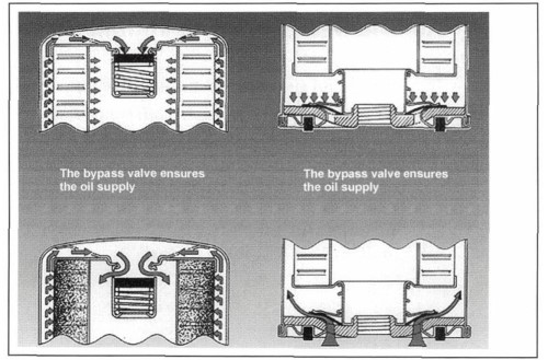
Fig. 8-4. Bypass valve and non-return valve for oil filters (Volkswagen)
The primary function of the oil filters is to protect the sliding partners from foreign particles in the oil. For this, the filter must be installed upline of the consumers so that the full oil flow passes through the filter (full-flow circuit). To relieve the full-flow filter and reduce its soiling, part of the oil is branched off from the main flow and is passed through a bypass filter—an oil centrifuge or a fine filter (Fig. 8-5).
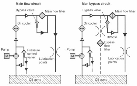
Fig. 8-5. Full-flow and full/bypass flow filtration
Bypass filters are not, however, an alternative to oil changes as they can neither replace used additives nor filter fuel, water, and acids out of the lubricant. If the engine oil is subject to high thermal loads, it has to be cooled separately, either with a water/oil or an air/oil heat exchanger.
The oil heat exchanger is normally installed downline of the filter to minimize the pressure loss in the filter with the still warm and, therefore, low-viscosity oil. For optimum protection of the engine, however, the filter should be located downline of the heat exchanger, i.e., immediately in front of the oil consumers.
From the filter or heat exchanger, the oil passes via the main oil channel to the oil consumers. The engine is supplied with oil from the main oil channel through bores in the crankcase intermediate walls and in the main bearing shells. It passes through bores in the crankshaft to the connecting rod bearings and from there—depending on the design—through a bore on the connecting rod to the piston pin bearing (Fig. 8-6).
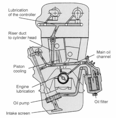
Fig. 8-6. Lubricating oil circuit (schematic) of a car SI engine (Volkswagen)
In order to deliver the oil to the main bearing journals, centrifugal force has to be overcome. On the other hand, delivery from the bore in the main bearing journal to that of the cam journal or to the pinion pin bearing is enhanced by the centrifugal force or by the oscillating movement of the connecting rod. As a rule, one main bearing should supply only one cam journal with oil.
In high-performance engines, the oil circuit is split into two channels, one supplying the camshaft control with oil under high pressure, the other supplying the camshaft bearings and bucket tappets with oil under low pressure.
The oil supply to engine parts such as belt tensioner bearings and to engine accessories such as exhaust turbocharger, fuel injection pumps, etc., comes directly via oil channels. Components not connected to the oil supply system such as rocker arm contact surfaces or the flanks of gear wheels are lubricated indirectly by the spray oil in the crankcase.
Under critical conditions, separate spray nozzles ensure an adequate supply of oil. The valve guides are also lubricated by sprayed oil, with the oil supply to the guides limited or metered by valve shaft seals. The trend today is towards more or less integrated oil lines and short oil paths with low pressure losses (hydraulic losses) (Fig. 8-7).
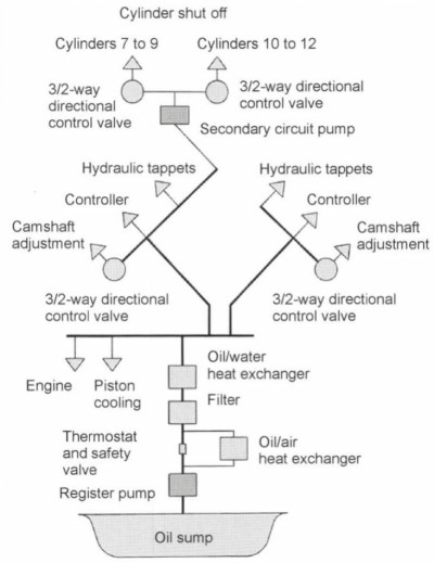
Fig. 8-7. Oil circuit of a V12 SI engine with cylinder shut-off (Mercedes-Benz)
For engines with high specific output, piston cooling is now indispensable. Lubricating oil is diverted from the main flow and injected through injection nozzles against the underside of the piston or into piston cooling channels for the piston cooling.
Pressure-controlled valves prevent heat being unnecessarily drawn from the piston when the engine, and hence the oil, is still cold. The spraying of the piston undersides through bores in the large connecting rod eye is a disadvantage because this cooling oil has to be additionally transported through the crankshaft.
As delivery begins only when the engine is started, there is a danger that the oil consumers receive no oil or too little oil during the first few revolutions of the engine. For this reason, nonreturn valves are fitted in risers and oil galleries in cylinder heads from which the collected oil can flow quickly to the consumers (Fig. 8-8). The electrically driven lubricating oil pilot pumps normally used on larger gasoline and large diesel motors cannot be used in motor vehicle engines because of the design complexity, the additional weight, and the cost.
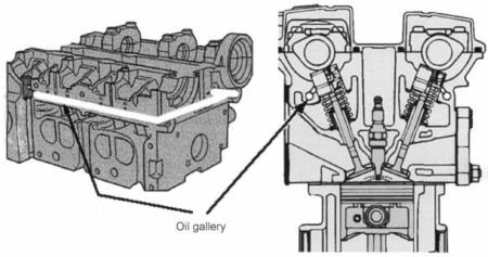
Fig. 8-8. Arrangement of the oil gallery in the cylinder head of a car SI engine (Ford)
Low oil levels and frequent oil circulation result in increased foaming of the oil. The upper limit for the gas content is considered to be 8%. Centrifugal separators and/or low-level oil return lines are used to counter foaming. As a result, the gas content can be reduced to below 4% (Fig. 8-9).
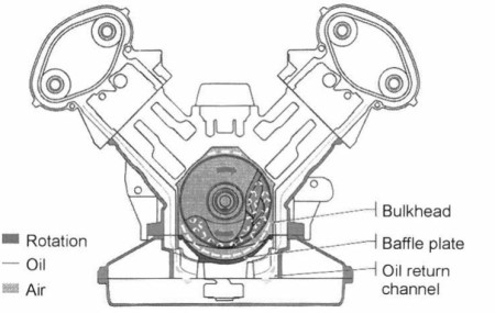
Fig. 8-9. Return oil passage from the cylinder heads of the Audi V6 Biturbo
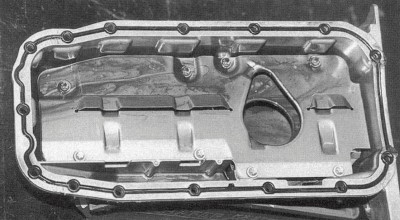
Fig. 8-10. Oil baffle plate of a four-cylinder car engine (Opel Ecotec)
The oil in the sump is kept away from the engine by oil baffle plates so that the crankshaft cannot become immersed in oil because of the sloshing of the oil caused by the vehicle movement (Fig. 8-10).
Date added: 2024-07-30; views: 848;