Control Mechanisms for Two-Stroke Cycle Engines
Characteristic of the principle behind the two-stroke cycle is that, in contrast to the four-stroke cycle, one complete working cycle is executed per crankshaft revolution; the expulsion of the burned charge from the cylinder and the introduction of fresh fuel and combustion air into the cylinder (scavenging process) takes place at crankshaft angles around BDC.
The requirement here is that, with a suitable design of the mechanism controlling the change of gases, there is minimum mixing of fresh gas and exhaust gas (high scavenging efficiency) with a low required scavenging pressure gradient (low work expenditure for changing the charge), all this within the smallest possible crankshaft angle range around BDC (limited restriction on the useful piston stroke). There are several different scavenging processes available for the change of charges in two-stroke engines; these are explained in greater detail in Section 10.3 (see also Refs. [1, 2]).
Their use requires a far different design for the drive components than what is found in four-stroke engines. Since the working cycle for the two-stroke engine transpires at the same frequency as crankshaft rotation, it is possible, in contrast to the four-stroke engine, to use the piston itself to control the gas flows.
Loop scavenging is used particularly in small engines and those running at high speeds; this principle is shown in Fig. 7-342. Here the piston controls the discharge of the exhaust from the cylinder through the exhaust slot(s), the inflow of fresh gas via the scavenging slots, and, when using the crankcase scavenging pump concept, the inlet of the fresh fuel-air mix into the crankcase as well.
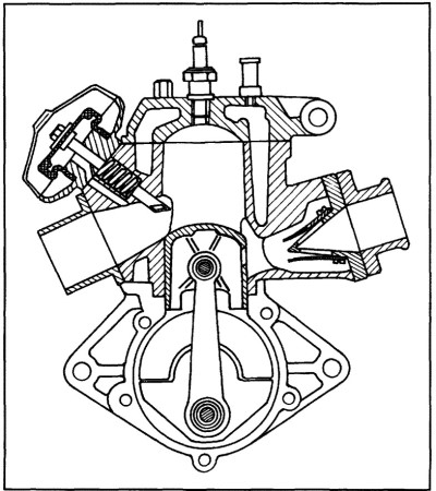
Fig. 7-342. Sectional view of a modern, two-stroke engine with loop scavenging, crankcase scavenging pump, reed valves at the intake system, and flat spool exhaust control
Because of the arrangement of the exhaust, intake, scavenging, and/or transfer passages at the cylinder, which penetrate the cylinder wall in the form of slots, the peculiarities described below result for the drive trains in two-stroke engines.
The slots in the cylinder wall make it more difficult to achieve defined lubrication of the tribologic pair— the piston and cylinder. To ensure adequate lubrication and to avoid unacceptably high oil consumption, engineers must exercise great care when selecting the mating materials in regard to minimum lubricating oil requirements, metered lubricating oil feed, and/or sufficient oil stripper effect by the piston rings.
To prevent the piston rings (and the ends in particular) from entering the exhaust, scavenging, and intake slots due to spring action, it is necessary to observe maximum slot widths (expressed as the ratio between slot width and cylinder diameter). This is explained in detail in Refs.
In addition, the slots, normally rectangular in shape, have to be rounded at the comers at the upper and lower ends, and the transitions from the cylinder to the channel walls have to be rounded. Piston ring rotation in the piston grooves, accompanied by the hazard that the ends of the rings enter the slots in the cylinder walls under spring pressure, is prevented where required by pins pressed into the ring grooves.
The fact that firing is twice as often as in four-stroke engines and, above all, the piston controls fresh gas and exhaust flow, results in far higher thermal loads on the piston and cylinder in slot-controlled two-stroke engines when compared with four-stroke designs. This is discussed in Ref. [4]. This loading is seen as the essential cause for the limited service life often found in high- performance two-stroke engines. The situation is made all the more difficult where the incoming air or mix passes through the crankcase (crankcase scavenging pump).
This largely eliminates effective cooling of the piston with splashed oil, a technique commonly used in higher- performance four-stroke engines. Among the strategies available to reduce the thermal load on the piston, piston rings, and wristpin boss are the following: Limiting individual cylinder volumes; careful designing of cylinder cooling (using water cooling if possible), particularly in the area around the exhaust slots; designing to reduce cylinder warping, which would make it more difficult to dissipate heat from the piston, through the piston rings, and to the cylinder walls; selecting a timing concept that prevents additional heating of the piston and fresh gas by exhaust blowback into the scavenging slots; selecting a scavenging process in which the exhaust flowing out of the cylinder is kept from coming into contact with any large surface area at the piston.
In modern loop scavenging cylinders for high-speed two-stroke engines, the fresh gas is generally introduced through between four and seven scavenging or transfer passages (in a mirror symmetrical arrangement to the exhaust channel), sweeping the wall at a shallow angle in the direction of the wall opposite the exhaust slot.
This causes a rising stream of fresh gas to be formed along the cylinder wall. Near the cylinder head it reverses direction and forces the exhaust gas out of the cylinder. The transfer passages are located at the side of the cylinder and are tapered slightly along the direction of flow.
This requires far more space between cylinders in multicylinder engines of this design when compared with similar four-stroke engines. The discontinuities in cylinder wall stiffness caused by the charge exchange runners results in more indirect force flow between the cylinder head and the crankshaft.
Consequently, the highly asymmetrical thermal loading on the piston and cylinder due to the exhaust slots make it necessary to very carefully design the drive assembly and its cooling. It should be noted here that various strategies are used particularly in modem, two stroke gasoline engines to increase the fresh gas fill efficiency, to influence fuel and air blending, and to avoid negative influences of gas pulsation in the intake and exhaust sections.
Depending on the concept employed, these may involve rotary intake valves, reed valves (oneway valves), bypass reed controls, oscillation chambers, and, on the exhaust side, control spools or cylindrical valves. This may increase the complexity of the drive system considerably.
When using uniflow scavenging with exhaust valves, a concept employed particularly in diesel engines is used— the fresh gas enters the cylinder through scavenging slots under cylinder control while the exhaust gas flows out through several valves located in the cylinder head; their opening is synchronized with crankshaft rotation frequency.
To achieve good scavenging efficiency, it is necessary that the intake runners or slots generally not impart any particular directional effect (aside from a slight tangential orientation to support gas blending); consequently, the volume of the intake plenum located upline from the scavenging slots, as shown in Fig. 7-343, in many cases adjoins the outside diameter of the cylinder sleeve (see also Ref. [5]).
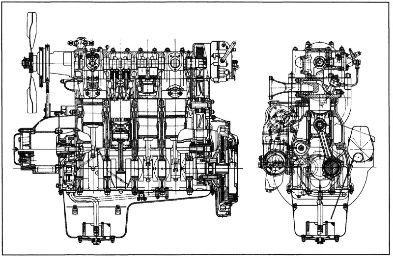
Fig. 7-343. Longitudinal and cross sections through a uniflow scavenged four-cylinder, two-stroke diesel engine made by Krupp
Since the scavenging slots have to be covered by the piston skirt at TDC, long pistons are required particularly in long-stroke engines, resulting in a relatively large overall height for the engine. In contrast to loop scavenging, uniform-flow scavenging using exhaust valves causes somewhat less and more symmetrical thermal loading at the piston and cylinder.
By contrast, the doubled actuation frequency for the exhaust valves (in comparison to four- stroke engines) and the high thermal loading on the cylinder head in fast-running engines places great demands on the design of cylinder head cooling and the kinematics of the valve train.
In the design with four exhaust valves, often selected for high-speed engines, one objective in development is to achieve a shallow contour for the runners (small runner surface to be cooled, low exhaust heat losses where an exhaust turbocharger is used) so that the exhaust gas flow at the individual valves is hindered as little as possible.
Aside from this, intensive cooling is necessary, particularly in the area around the injection nozzle to avoid carbonization problems. In order to exchange the charges—within the limited crankshaft arc available for this purpose—with the smallest possible amount of work, one must select a suitable valve train concept and valve train kinematics inducing minimum pressure loss as gases flow through the valves.
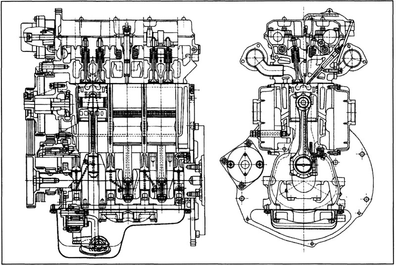
Fig. 7-344. Longitudinal and cross sections through a uniflow scavenged, two-stroke diesel engine made by AVL for passenger cars
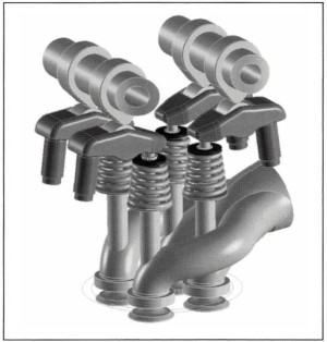
Fig. 7-345. Illustration of the exhaust runner configuration and the valve train for a uniflow-scavenged, two-stroke diesel engine for passenger cars
Figure 7-344 shows the solution used in a 1.0-liter, two-stroke diesel engine currently being built by AVL. In this engine, the four exhaust valves at each cylinder are activated by roller cam followers at two overhead camshafts. Figure 7-345 shows an alternate exhaust runner version to this concept.
Date added: 2024-07-30; views: 658;