Rotation-Angle-Controlled Tightening
When tightening the nut using the rotation angle as the lead variable, through to the 0.2% offset limit, the preload value is on average from 25% to 30% higher than for torque-controlled tightening. While in torque-controlled tightening the preload force varies by about ±25% (practically to the same extent as the friction), the preload force where the rotation angle or 0.2% offset limit is used as the lead variable varies by only about ±10%.
When tightening using rotation control, the spread in preload is dependent on friction only in the range up to the snug-tight torque. The snug-tight torque is the moment that has to be applied until, by tightening the connection, all the mating surfaces are seated solidly one against another due to elastic and plastic deformation.
The spread results primarily from the differing 0.2% offset limits for the bolts, provided that the required repetition accuracy when approaching the set angle is achieved. This is the case in today’s pulse transducers. Beyond that, we see from the progress of the curves above the 0.2% offset limit that angular scatter has only a subordinate influence on assembly preload (Fig. 7-332). Torque monitoring is used to ensure quality in the connection.
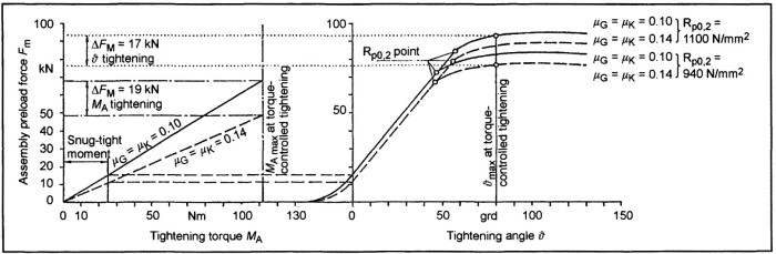
Fig. 7-332. Tightening curve for a screw as per DIN EN ISO 24014—M 12 × 1.5 × 70—10.9—for control by torque (left) and control with rotation angle and 0.2% offset limit (right), illustrating the influences of thread and head friction and screw strength
We see that when tightening under torque control, the minimum preload force Fm lies between 48 and 57 kN. When working with yield point (0.2% offset limit) control, this value is between 67 and 85 kN while rotation angle control yields between 77 and 94 kN. Consequently, tightening under torque control gives the greatest spread in preload force at the smallest preload level. The preload force level when using tum-of-the-nut tightening is on average about 10% greater than that for the yield point technique.
The area around the Rp0.2. points represents the window for tightening under yield point control. The switch- off point for the power driver has to lie within this area so that the threaded connection is registered as “OK” and can receive the paint marking, if that is specified.
When dimensioning threaded connections, it is necessary to remember that a threaded connector, in the event of overloading due to static tensile forces, breaks at its weakest point. This is normally the case in the nonengaged threaded section or in the waisted-shank area.
Using the tum-of-the-nut process (as a process that goes beyond the elongation limit) is not critical in screws and bolts where the shank length is greater than 2 x d or there are more than 10 turns of nonengaged threading. In that case, even tolerances as great as 20° are acceptable when specifying the rotation angle used for tightening. In a threaded connector with a pitch of P = 1.5 mm, turning the screw by 30° beyond the 0.2% offset limit induces plastic elongation of about 0.125 mm.
Referenced to the 60 mm effective clamping length (grip) this represents permanent deformation of 0.21%. This value is not critical. Conversely, when using short screws (<2 x d shank length) the switch-off point has to be specified so closely that it is very near the yield point, particularly since today screws are often tightened into the offset limit range.
The rule of thumb is that in these cases, referenced to the grip length, a maximum of 1% permanent deformation is acceptable. It is necessary to note here, however, that if the screw is tightened several times, then the head contact surface and the engaged threads can be damaged and thus tend to scuff and possibly seize. The required preload force cannot be attained in this event.
A further advantage of rotation-controlled tightening is its reproducibility even when using simple tools; consequently, it is a favorite technique for initial tightening on the assembly line and for service work.
Bibliography: [1] Jende, S., "Robotergerechte Schrauben–Hochfeste Verbindungselemente für flexible Automaten," Techno TIP, 12/84, Vogel-Buchverlag, Würzburg.
[2] N.N., Industriewerkzeuge–Montagewerkzeuge, 2000–2001 catalog, Atlas Copco Tools GmbH, Essen.
[2a] N.N., Schraub- und Einpresssysteme. Firmenkatalog der Robert Bosch GmbH Automationstechnik, Edition 1.1, 2001, Murrhardt.
[3] VDA Publications, "Qualitätsmanagement in der Automobilindustrie," Qualitätsmanagement-Systemauditm Vol. 6, Part 1, 1998 edition, Verband der Automobilindustrie, Frankfurt.
[4] Jende, S., and W. Mages, "Roboterschrauben. Wie sollen Roboterschrauben gestaltet sein?" Schriftreihe Angewandte Technik, Verlag für Technikliteratur, 1990, pp. 12–18.
[5] Jende, S., "Automatische Montage hochfester Schrauben–Anwendungsbeispiele aus der Praxis," wt–Zeitschrift für industrielle Fertigung, Springer-Verlag, Berlin, Heidelberg, 1986.
[6] N.N., "Informations-Centrum Schrauben–Automatische Schraubmontage," Deutscher Schraubenverband e.V. [ed.], Hagen, 2nd edition, Mönning-Druck, Iserlohn, 1997.
Date added: 2024-07-30; views: 626;