Conrod Bolt
The conrod bolt represents a typical case for a threaded connection subject to high dynamic loading. The range of sizes in passenger car engines is from M 7 to M 9, for utility vehicle engines from M 11 X 1.5, M 12 X 1.25, M 14 X 1.5, to M 16 X 1.5.
To achieve correct dimensioning of the conrod bolt, one draws on data from the predecessor engine or for engines of similar design and size. Concerning the bolt for the large conrod eye, the operational loading on the bearing case due to the physical forces acting on the crankshaft system (masses and gas forces) are known.
Not known at the outset, however, are the operational loads by size, direction, and location, referenced to the bolt centerline in the parting plane and introduced into the individual threaded connection; this information is needed to ascertain the deformations and loads for the bolt. The professional literature mentions various analytical procedures used to calculate the axial force FA, the transverse force FQ (calculated magnitude derived from the friction value in the parting plane), and the eccentric distance a for the axial force from the screw centerline, dependent on the design parameters of the conrod bearing case.
If these values are available, then it is possible, using the “KABOLT” program, which runs on a PC (screw calculations as per VDI 2230), to determine the preload value required to prevent partial liftoff and lateral shift of the connected components, and thus, to ascertain the appropriate thread dimensions and the strength class for the bolt. The determined values are used to designate the specifications for bolt tightening.
Once the design calculations for the conrod joint have been concluded, pulser tests are used for the entire connecting rod to demonstrate durability. Subsequently, the calculated and laboratory results are verified with testing in the field. The calculation parameters for a conrod bolt connection are shown in Fig. 7-327. The example refers to a four-cylinder gasoline engine with displacement of 1996 cm3.
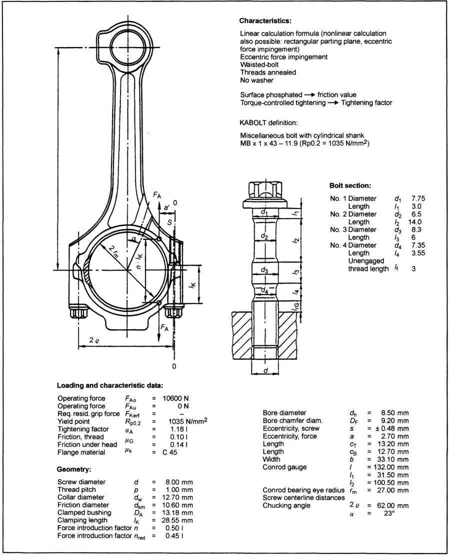
Fig. 7-327. Relationships in the conrod bolt
The conrod bolt design is based primarily on the loading and on the assembly of the conrod. Depending on whether or not a nut is used, the bolts are equipped with heads shaped to accommodate torque transmission or with antirotation devices. The two halves of the conrod are centered with knurling, a fitting bushing, or a separate spline. Large conrods in utility vehicles often use interlocking areas following the tongue-and-groove principle.
The use of a sintered conrod makes good sense when a particular model is manufactured in medium-range numbers. While in conventional manufacture, the large conrod eye is cut away after machining in order to mount the conrod bearing shells. In recent years, “cracking” has established itself in large-volume manufacturing of sintered, cast, and forged conrods.
Here the conrod end is separated from the conrod shaft in a device that applies a defined, external load to areas laid out to promote fracture. The advantage, in addition to eliminating the cutting work, is that the two halves of the conrod are selfcentering. Then the fracture surfaces (postassembly) can be used to permit turning out the bearing shell seats. That is why a cracked conrod does not require an exact fit for the shaft at the conrod bolt. Here the screw diameter may exhibit a tolerance of 0.1 mm.
Each conrod is assembled twice after cutting. The first time is in preparation for machining the seats for the bearing shell. Here the preload force used for assembly must be similar to that found later during operation, so that similar deformations are induced in the conrod bearing housing. It is for this reason that the bolts are tightened to just below the 0.2% offset limit under torque or rotation angle control or under direct offset limit control.
The conrod is disassembled after machining (to insert the bearing shells) and is then mounted on the crankshaft. Here a rotation angle controlled tightening process is used, which tightens the bolt into the range beyond the elastic limit; alternately, tightening under 0.2% offset limit control is employed. If one decides in favor of the rotation angle as the control magnitude, then it is necessary to conduct extensive laboratory trials in advance in order to formulate specifications for tightening. When using the 0.2% offset limit as the lead magnitude, it is sufficient, in a few tightening trials, to define the so-called “window.”
Particularly because the conrod bolt, because of the manufacturing process for the conrod, has to be assembled twice and tightened into the offset limit range, one must ask which screws are particularly suitable for tightening beyond the 0.2% offset limit.
When dimensioning threaded connections, it is necessary to remember that the threaded section, in the event of overloading due to static tensile forces, breaks at its weakest point. This is normally the case in the nonengaged threaded section or in the waisted-shank area. In the multiwaisted bolts recently developed, the failure is also in a waisted area. The conrod bolts shown in Fig. 7-328 are particularly suited for tightening into the range beyond the elastic limit.
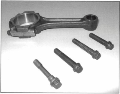
Fig. 7-328. Conrod bolts for tightening beyond the elastic limit
When using bolts with a shaft (similar to DIN EN 24014), there should be at least six nonengaged turns in order to distribute plastic elongation over a larger area and, thus, to avoid the hazard of premature narrowing. The best tightening properties in the range beyond the elastic limit are demonstrated by waisted-shank bolts and screws that are threaded right up to the head (similar to DIN/EN 24017). The measured flexibility places the multiwaisted bolts between the waisted-shank bolt and the screw that is threaded along its full length.
The durability of threaded connections is determined exclusively by the magnitude of local stress concentrations. In bolt materials the fracture strength of the notched area compared to the smooth rod should, as a rule, be greater than 1, indicating a material with sufficient ductility. Permissible in high-strength bolts are durability values in the pulsating tensile range of QA = ±55 N/mm.
Screw durability is increased if the threads are rolled after annealing. The additional dynamic forces resulting from dynamic operational forces (which are absorbed by the screw) are lowered (in connection with eccentric loading) as the preload force level gets higher. This, too, favors a tightening process that goes beyond the elastic limit.
Date added: 2024-07-30; views: 621;