Fluid flow in closed pipes. Nozzles. Dali tube
Differential-pressure devices. Differential pressure devices using a constriction in the pipeline have been the most common technique for measuring fluid flow. Recently, other devices have made substantial inroads in the basic measurement of fluids. Differential pressure is still a widely used technique, with even some new devices that have been introduced in the recent past. A recent estimate puts the use of differential pressure devices to measure flow in the petrochemical industry at over 70 percent of all flow devices.
As already shown in the derivation of Bernoulli’s equation in the previous section, a constriction will cause an increase in fluid velocity in the area of that constriction, which in turn will result in a corresponding pressure drop across the constriction. This differential pressure (d. p.) is a function of the flow velocity and density of the fluid and is shown to be a square root relationship; see equation (І.24).
A flowmeter in this category would normally comprise a primary element to develop a differential pressure and a secondary element to measure it. The secondary element is effectively a pressure transducer, and operational techniques are discussed in Chapter 9, so no further coverage will be given here. However there are various types of primary element and these deserve further consideration. The main types of interest are; orifice plate, venturi, nozzle, Dali, rotameter, gate meter. Gilflo element, target meter, and V-Cone.
Orifice plate. An orifice plate in its simplest form is a thin steel plate with a circular orifice of known dimensions located centrally in the plate. This is termed a concentric orifice plate; see Figure 1.5(a). The plate would normally be clamped between adjacent flange fittings in a pipeline, a vent hole and drain hole being provided to prevent solids building up and gas pockets developing in the system; see Figure 1.5(b).
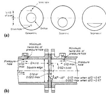
Figure 1.5. (a) Orifice plate types, (b) Concentric orifice plate with D and D/2 tappings mounted between flange plates. Courtesy, British Standards Institution
The differential pressure is measured by suitably located pressure tappings on the pipeline on either side of the orifice plate. These may be located in various positions depending on the application (e.g., corner, D and D/2, or flange tappings), and reference should be made to BS 1042 Part 1 1964 for correct application. Flow rate is determined from equation (1.24).
This type of orifice plate is inadequate to cope with difficult conditions experienced in metering dirty or viscous fluids and gives a poor disposal rate of condensate in flowing steam and vapors.
Several design modifications can overcome these problems in the form of segmental or eccentric orifice plates as shown in Figure 1.5(a).
The segmental orifice provides a method for measuring the flow of liquids with solids in suspension. It takes the form of a plate that covers the upper cross-section of the pipe leaving the lower portion open for the passage of solids to prevent their build-up.
The eccentric orifice is used on installations where condensed liquids are present in gas-flow measurement or where undissolved gases are present in the measurement of liquid flow. It is also useful where pipeline drainage is required.
Venturi tube. The classical venturi tube is shown in Figure 1.6. It comprises a cylindrical inlet section followed by a convergent entrance into a cylindrical throat and a divergent outlet section. A complete specification may be found by reference to BS 1042 Part 1 1964 and relevant details are repeated here:
(a) Diameter of throat. The diameter d of the throat shall be not less than 0.224D and not greater than 0.742D, where D is the entrance diameter.
(b) Length of throat. The throat shall have a length of 1.0 d.
(c) Cylindrical entrance section. This section shall have an internal diameter D and a length of not less than 1.0 d.
(d) Conical section. This shall have a taper of 10|°. Its length is therefore 2.70(0 — d) within ±0.24(D — d).
(e) Divergent outlet section. The outlet section shall have an inclined angle of not less than 5° and not greater than 15°. Its length shall be such that the exit diameter is not less than 1.5 d.
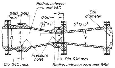
Figure 1.6. Venturi tube. Courtesy, British Standards Institution
In operation the fluid passes through the convergent entrance, increasing velocity as it does so, resulting in a differential pressure between the inlet and throat. This differential pressure is monitored in the same way as for the orifice plate, the relationship between flow rale and differential being as defined in equation (1.24).
Location of pressure tappings. The upstream pressure tapping is located in the cylindrical entrance section of the tube 0.5D upstream of the convergent section and the downstream pressure tapping is located in the throat at a distance 0.5 D downstream of the convergent section. Pressure tappings should be sized so as to avoid accidental blockage.
Generally the tappings are not in the form of a single hole but several equally spaced holes connected together in the form of an annular ring sometimes called a piezometer ring. This has the advantage of giving a true mean value of pressure at the measuring section.
Application. The venturi is used for applications where there is a high solids content or where high pressure recovery is desirable. The venturi is inherently a low head-loss device and can result in an appreciable saving of energy.
To sum up the venturi tube:
Advantages
1. Simple in operation
2. Low head loss
3. Tolerance of high solids content
4. Long-term reliability
5. No moving parts
Disadvantages
1. Expensive
2. Square root pressure-velocity relationship
3. Poor turn-down ratio
4. Critical installation requirements
Nozzles. Dali tube
The other most common use of the venturi effect is the venturi nozzle.
Venturi nozzle. This is in effect a shortened venturi tube. The entrance cone is much shorter and has a curved profile. The inlet pressure tap is located at the mouth of the inlet cone and the low-pressure tap in the plane of minimum section as shown in Figure 1.7. This reduction in size is taken a stage further in the flow nozzle.
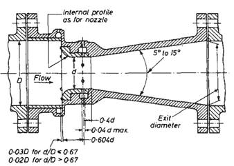
Figure 1.7. Venturi nozzle. Courtesy, British Standards Institution
Flow nozzle. Overall length is again reduced greatly. The entrance cone is bell-shaped and there is no exit cone. This is illustrated in Figure 1.8. The flow nozzle is not suitable for viscous liquids but for other applications it is considerably cheaper than the standard venturi tube. Also, due to the smooth entrance cone there is less resistance to fluid flow through the nozzle and a lower value of m may be used for a given rate of flow. Its main area of use therefore is in high-velocity mains where it will produce a substantially smaller pressure drop than an orifice plate of similar m number.
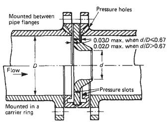
Figure 1.8. Flow nozzle. Courtesy, British Standards Institution
Dali tube. This is another variation of the venturi tube and gives a higher differential pressure but a lower head loss than the conventional venturi tube. Figure 1.9 shows a cross-section of a typical Dali flow tube. It consists of a short straight inlet section, a convergent entrance section, a narrow throat annulus and a short divergent recovery cone. The whole device is about 2 pipe-diameters long.
A shortened version of the Dali tube, the Dali orifice or insert, is also available; it is only 0.3 pipe-diameter long. All the essential Dali tube features are retained in a truncated format as shown in Figure 1.10. Venturi tubes, venturi nozzles, Dali tubes, and other modifications of the venturi effect are rarely used outside of the municipal wastewater industry and the mining industry.
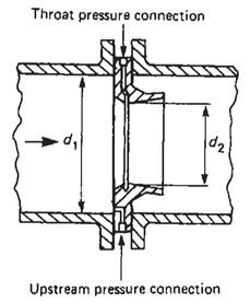
Figure 1.10. Dali insert. Courtesy, British Standards Institution
There is even a version of a venturi tube combined with a venturi flume called a DataGator that is useful for any pipe, full or not. In this device, the inlet fills up simultaneously with the throat, permitting measurement in subcritical flow as if the device were a venturi flume, and above critical flow' as if the device were a venturi tube. In the ‘transition zone’ between sub- and super-critical flow, the design of the unit permits a reasonably accurate measurement. This design won an R&D100 Award in 1993 as one of the 100 most important engineering innovations of the year.
Pressure loss. All the differential pressure devices discussed so far cause an irrecoverable pressure loss of varying degree. In operation it is advantageous to keep this loss as low as possible, and this will often be a major factor in the selection criteria of a primary element. The pressure loss curves for nozzles, orifices, and venturi tubes are given in Figure 1.11.
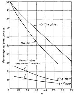
Figure 1.11. Net pressure loss as a percentage of pressure difference. Courtesy, British Standards Institution
Installation requirements. As already indicated, installation requirements for differential-pressure devices are quite critical. It is advisable to install primary elements as far downstream as possible from flow disturbances, such as bends, valves, and reducers. These requirements are tabulated in considerable detail in BS 1042 Part 1 1964 and are reproduced in part in Appendix 1.1. It is critical for the instrument engineer to be aware that these requirements are "rules of thumb”, and even slavish adherence to them may not produce measurement free from hydraulics-induced error.
From a practical point of view, the best measurement is the one with the longest upstream straight run, and the longest downstream straight run.
Date added: 2023-05-02; views: 868;