Valve Keepers. Tasks and Functioning
Tasks and Functioning. The purpose fulfilled by valve keepers is joining the valve spring collar with the valve in such a way that the valve spring always keeps the valve in the required position.
Cold-embossed valve keepers are state of the art for valve stems up to 12.7 mm in diameter. The CIO and/or SAE1010 qualities are used.
The valve keepers are classified according to their function as follows:
- Clamping connection creating a frictional connection among the valve, the valve keeper, and the valve spring collar
- Nonclamping connection, which allows for unrestricted valve rotation
Clamping connections. Clamping valve keepers transfer force through a frictional connection. To achieve this, it is necessary that a narrow gap be maintained between the two halves of the valve keeper. That is why valve keepers with conical angles of 14°, 15°, and 10° are used. Valve keepers with smaller conical angles bring about far more intensive clamping action. They are suitable particularly for engines that run at extremely high speeds. Where the clamped connections are heavily loaded, the use of case-hardened (480 to 610 HV 1) or nitrided (≥400 HV 1) valve keepers is recommended.
Figure 7-146 shows an example of a clamping valve keeper in its installed position.
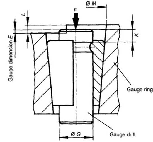
Fig. 7-146. Installation principle for valve keepers
Nonclamping connections. A nonclamping connection is achieved by using valve keepers with a conical angle of 14° 15'. Because of the fact that the two halves of the valve keeper, when installed, rest against each other at flat surfaces, they provide clearance between the valve keeper halves and the valve stem.
This allows the valve to rotate in the spring collar. Rotation is supported by vibration, by eccentric contact between the rocker arm and the end of the valve stem, and by the impetus provided by valve lifter rotation.
When a nonclamping connection is used, the forces along the axial direction are transferred by the three or four beads inside the valve keeper. That is why case hardening the valve keeper is indispensable. Figure 7-147 shows an example of a clamping valve keeper when installed.
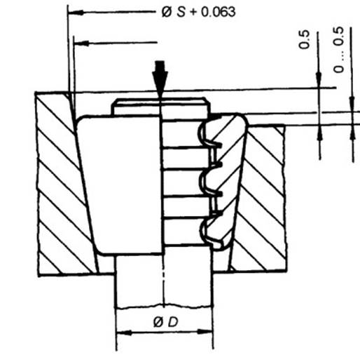
Fig. 7-147. Installation principle for valve keepers with clearance to prevent clamping
Manufacturing Techniques. Valve keepers are cold pressed from profiled strip steel. Multislot valve keepers are always case hardened and ground at their mating planes. Other versions may be used without hardening or with case hardening, or they may be nitrided, as desired. Manufacturing may require that the outside jacket, about halfway down the side, be made concave by as much as 0.06 mm, the amount depending on the exact design. The outside jacket may never be convex.
In free-rotation, multislot valve keepers’ correct valve stem clearance is achieved by dimensioning 0.06 mm smaller than the nominal diameter.
The conical section in the spring collar has to be long enough that the valve keeper does not hang over at either end when installed. The conical jacket may in no case be convex and should serve as the reference surface for the dimensional and positioning tolerances in the spring collar.
Date added: 2024-05-12; views: 978;