Valve Springs. Determining Strain under Load
The purpose of the valve spring is to close the valve in a controlled fashion. This requires maintaining constant contact among valve train components during valve movement. In the “valve closed” state, the spring force F1 must be great enough to keep the valve from bouncing on the valve seat immediately after closing. In the “valve open” state, it is necessary to prevent “fly-over,” i.e., the valve stem lifting off and breaking contact with the cam at maximum deceleration.
The kinematics are such that the required spring force F2 is the product of the valve’s mass and the maximum valve deceleration αmax
When engineering the valve springs, additional, and sometimes conflicting, objectives are to be achieved:
- Reducing spring forces: Among other factors, fuel consumption can be influenced by the engine’s internal friction. The friction losses occurring in the valve train are proportional to the required spring forces. The maximum required spring forces are determined by the inertia of the moving valve train components, from the cam lobe to the valve.
Consequently, the mass of the spring, the cam lobe contour, and maximum camshaft rotation speed are influencing factors. A reduction in spring mass can be influenced by increasing vibration resistance and optimizing the shape of the valve spring.
- Reducing height: Reducing the height of the assembly can also have a positive effect on fuel consumption. On the one hand, this provides greater latitude for the design of the hood and improving vehicle aerodynamics. On the other hand, reducing the height of the assembly is another key to reducing engine weight. The design of the valve spring and an increase of its fatigue limit can have a favorable influence on assembly height.
- Ensuring minimum failure rates: The increased demands on the valve springs unavoidably lead to an increase in operational strength. In the course of an engine’s service life, at about 200 000 km, the spring has to withstand up to 300 million loading cycles. At the same time, only a miniscule spring failure rate is acceptable.
The use of multivalve technology makes it necessary to further reduce the failure rate for individual springs. If one assumes, for example, a failure rate of just 1 ppm for the valve springs and if one is building a 24-valve engine, then the result is that, at maximum, only one engine in 40000 will fail as a result of valve spring failure. Ensuring low failure rates imposes stiff demands on valve spring design, materials, and production.
- Economy of product improvement: The demands presented here have to be economically justifiable; i.e., the benefit associated with any given measure has to be greater than any additional costs that might be incurred. This challenge has been taken up by valve spring manufacturers in the face of increasingly tougher competition.
Determining Strain under Load. Fundamentally, the loading on a coiled compression spring is that of a rod subjected to torsion. When torsional moment Mt is applied as is shown in Fig. 7-150, two shearing strains τ are induced in the longitudinal and transverse sections. According to Mohr’s circle, these shearing strains can be assigned to two primary direct stresses σ1 and σ2 at less than 45°
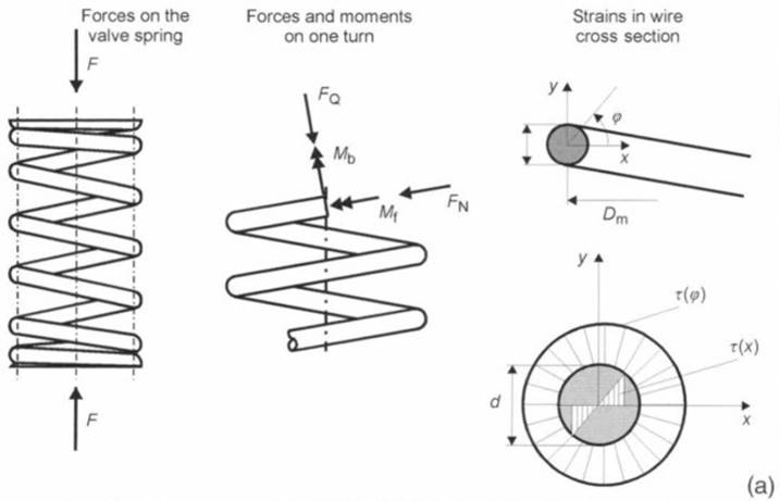
Fig. 7-150 (a). Forces, moments, and strains in valve springs
Whereas pure shear stress load is induced in the torsion bar, the situation in a coiled spring is different. Because of the spring’s geometry and the potential deviation of the effective force axis from the spring’s centerline, the bending moment Mb, the lateral force Q, and the standard force N can generate additional stresses under load. Moreover, because of the curvature of the wire, the strains along the circumference are not uniform. Maximum load tensions thus occur on the inside of springs made of round wire.
The equations used to calculate helical compression springs are given in DIN 2089. The following situations apply to the spring rate R, the force F, and the torsional strain τ:
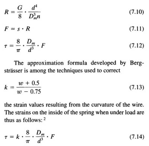
The shear stresses determined analytically do not take into account the additional load strains previously mentioned, which result from the bending moment and the transverse and standard forces. In addition, the spring’s natural vibrations at high engine speeds cause dynamic overshooting to values that can exceed by as much as 50% the load strains determined in static testing.
These dynamic effects can be ascertained either with multibody simulation programs or by metrologically using strain gauges. The experiments are usually performed on specially prepared engine mockups. The resulting tracing shows the load strain plotted against engine speed and crankshaft angle.
Depending on the loading and the limitations imposed by available installation space, the shapes shown in Fig. 7-150b have been developed. The standard shape is the symmetrical, cylindrical spring. In this spring the distances between the turns are symmetrical at both ends of the spring, and the diameter of the turns is constant. Progression in the spring characteristics is achieved by the partial contact of the turns across the spring deflection path.
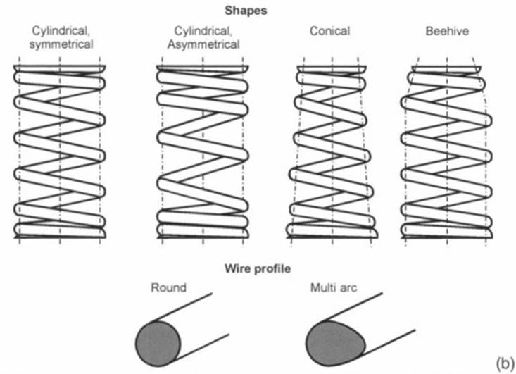
Fig. 7-150 (b). Valve spring shapes and wire profiles
Depending on the progression engineered into the spring, the spring rate and the spring’s natural frequency may change across the spring deflection path. The dynamic excitation of the spring thus becomes broader in spectrum, and dynamic overshooting is reduced.
The spring may be wound asymmetrically in order to keep the spring masses in motion as small as possible. This means that the closely spaced turns required for progression are located toward the cylinder head. The disadvantage of the asymmetrically wound spring is that additional measures have to be implemented to ensure that the spring is properly oriented for mounting in the cylinder head.
The conical valve spring offers the advantage that, on the one hand, the moving masses are smaller than for a cylindrical spring and, on the other hand, the fully compressed height is slightly shorter. Furthermore, a conical spring permits the use of a smaller spring collar at the valve, which in turn has a positive influence on the masses in motion. A disadvantage is that a conical spring often exhibits less progression than a cylindrical spring.
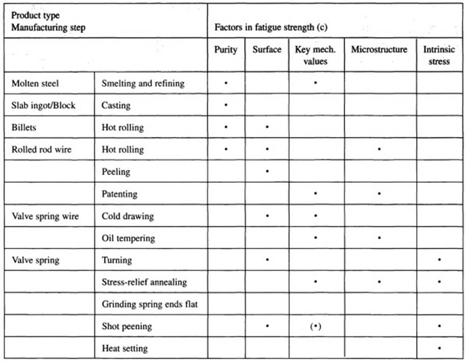
Fig. 7-150 (c). Factors affecting valve spring fatigue strength
The so-called “beehive spring” comprises a cylindrical section fixed in place and a conical section in contact with the spring collar. This shape is always used when the integrated valve stem seal precludes using a strictly conical spring shape. In this way, the masses in motion can be reduced significantly by employing a spring collar smaller than the one used with a cylindrical spring. The required degree of progression can be determined in the cylindrical section.
Round and multiarc (“egg-shaped”) wires are the shapes normally used. With the multiarc wire one has, in addition, the benefits of reduced installation height and more uniform distribution of strains across the wire’s cross section. This is in contrast to round wire, which, as mentioned above, is subjected to the greatest stress on the inside of the spring. Ideal utilization of the material’s properties is achieved with the wire cross sections as analyzed by Yamomoto.
This cross section provides, on the one hand, the equivalent diameter of a round wire and the axial ratio of the two primary axes. Thus “3.8 MA 25” designates a multiarc wire whose axial ratio is 1:1.25 and whose polar geometrical moment of inertia corresponds to that of a round wire 3.8 mm in diameter.
The low failure rates required here place the maximum demands on the material used to make valve springs. Primary reasons for valve failure are found in nonmetallic inclusions in the spring wire or in mechanical damage to the surface. The Cr-V steels which were often used in the past can no longer satisfy the demands for tensile strength as found in heavily loaded valve springs.
They have largely been supplanted in Europe by Cr-Si alloys. Cr-Si steels, in comparison with Cr-V steels, exhibit fewer nonmetallic inclusions and greater tensile strength. Being used to an even greater extent is HT (high-tensile) wire alloyed with Cr-Si-V or Cr-Si-Ni-V.
The wire rod is peeled prior to cold drawing in order to achieve a wire that is free of surface defects. The required degree of strength is attained by a hardening process; this is usually oil tempering, but inductive hardening may also be used. Following hardening, eddy current sensors are used to check the wire for surface defects. Any faulty areas are marked, and the wire is rejected before it goes to the spring manufacturing process.
After the spring has been turned, it is stress-relief annealed to reduce the internal strains in the turns. Finally, the ends of the spring are ground flat to ensure that they are parallel with their mating surfaces. The spring may be chamfered, depending on the specifics of the application.
The ball blasting process may be used to compact the surface and to introduce residual compressive force in the areas near the surface. The tensile stresses occurring during operation are superimposed on these intrinsic compression stresses and prevent fissure propagation.
To further increase fatigue strength, springs subject to severe loading are hardened as well. In this way, the amount of stress that can be handled is increased significantly, by about 10%, when compared with conventional springs.
Moreover, valve springs are nitrided for some applications and then shot peened once again. Because of the costs associated with this process, it has not yet been used in either Europe or North America.
Bibliography:
1) Muhr, T., “Zur Konstruktion von Ventilfedem in hochbeanspruchten Verbrennungsmotoren,” Dissertation, RWTH Aachen, 1992.
2)Deutsches Institut fur Normung e.V [ed.], Zylindrische Schrauben- druckfedern aus runden Staben, 7th edition, DIN 2089 (Part 1), Beuth Publishers, DIN Pocket Books, Berlin, 1984.
3) Niepage, P., “Messstellenermittlung und Messwertkalibrierung zur Spannungmessung an Ventilfedem mittels Dehnungsmessstreifen,” Draht, Vol. 41, 1990, No. 3, pp. 333-336.
4) Yamamoto, “Valve Spring Made by Sankos Multi-Arc Wire,” Sanko Senzai Kogyo Co. Ltd., Kyoto, 1989.
Date added: 2024-05-12; views: 750;