Geometry and Tolerances. Typical valve seat insert contour
Valve seat inserts, in general, exhibit a simple ring shape. Special shapes with contoured exterior surfaces are used for components that are cast in place during cylinder head manufacture. These contours are intended to create a positive connection, to keep the valve seat inserts from being dislocated. Figure 7-162 shows a typical contour for a valve seat insert. Figure 7-163 summarizes common tolerance values.
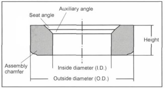
Fig. 7-162. Typical valve seat insert contour
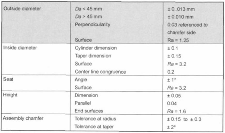
Fig. 7-163. Tolerance ranges in valve seat engineering
- Valve seat: The valve seat in the insert is the actual functional area for this component. As a rule, final finishing by milling is carried out only after the component has been mounted in the cylinder head so as to achieve exact congruence of the valve axis and the valve seat insert axis (centerline offset of 0.02 to 0.03 mm in new engines).
Two engineering options available to reduce wear at the valve seat are found in reducing the valve seat angle and increasing the width of the valve seat. Reducing the valve seat angle or widening the valve seat reduces the loads that are effective parallel to the seating surface, as is depicted in Fig. 7-164.
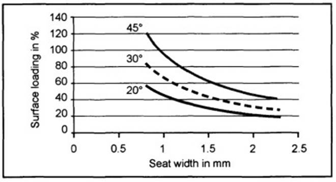
Fig. 7-164. Comparison of surface loading depending on valve seat angle and width
Investigations have revealed that reducing longitudinal surface loading results in a reduction of the wear rate. Common values for the valve seat angle and valve seat widths are given in Fig. 7-165.
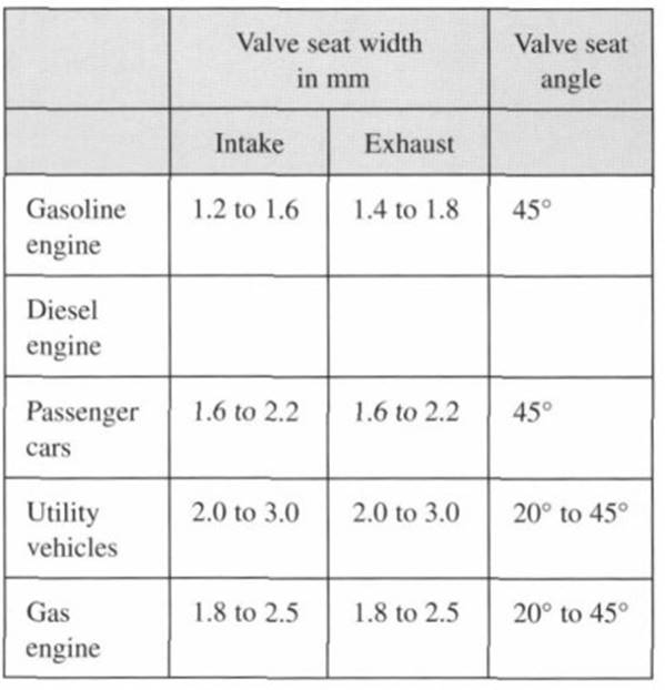
Fig. 7-165. Valve seat widths and angles
- Installation chamfer: The chamfer positions the valve seat insert and lowers the forces required for pressing it in place, prior to and while mounting in the cylinder head. Turned chamfers are normally a simple sloped area with an angle of from 10° to 45°. When valve seat inserts are formed in a powder metallic production process, the chamfers that are imparted are often rounded, with radii of from 0.4 to 1.4 mm, and with an area sloped by 10° to 15° on the outside surface.
It may be assumed in principle that smaller angles for the sloped areas result in lower assembly forces. In addition, it is necessary to ensure that no burrs are created at the assembly surface during milling. This is prevented by fine grinding of the components.
- Inside diameters: The inside diameter of valve seat inserts are generally not machined. To optimize gas flow patterns, the inner surfaces of intake valve seating rings in certain families of motors are specially shaped to impart Venturi contours, for example.
To improve run-in conditions and to achieve constant valve seat widths following final machining of the valve seat insert (in the cylinder head), subordinate angles are often provided at the valve seat area. The normal value for such angles is 30° (Fig. 7-166).
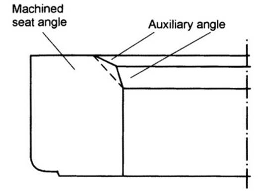
Fig. 7-166. Subordinate angles
- Wall thickness: More compact designs for modern engines impose demands for thinner walls at the valve seat inserts. This is limited by the mechanical loading on the valve seat insert and by aspects associated with production reliability. The wall thicknesses normally produced in mass production exceed 1.8 mm. The ratio of height to wall thickness should be as is shown in Fig. 7-167.
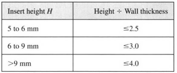
Fig. 7-167. H:W ratio
- Outside diameter: To achieve a sufficiently tight press fit in the cylinder head, the insert is usually from 0.05 to 0.13 mm shorter than the bore in the cylinder head. A further orientation value for the design of aluminum cylinder head assemblies is calculated as follows: Insert length differential = 0.3% to 0.4% of the diameter of the bore in the cylinder head. The amount of excess length should always be selected to suit the particulars of the application.
Transferring heat to the cylinder head requires good contact with the inside diameter of the cylinder head bore, particularly at the face toward the combustion chamber, since it is here that the greatest amount of heat transfer takes place.
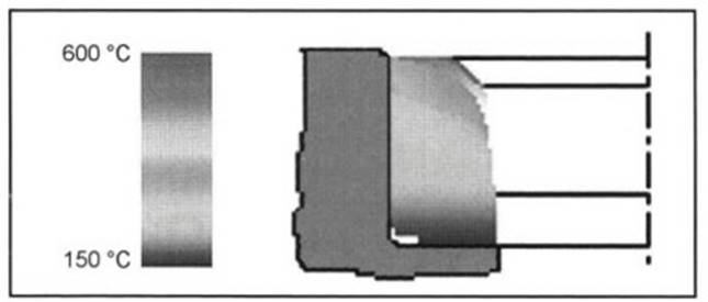
Fig. 7-168. Temperature distribution inside a valve seat insert at the exhaust port
Figure 7-168 shows the temperature distribution inside a valve seat insert at the exhaust port. When valve seat inserts are made using powdered metal technology it is necessary to ensure that the ratio of the outside diameter to the wall thickness is in a rang of from 10 to 13. This is necessary to ensure sufficient “green-body” stability in the powder blanks before they are sintered. No such limitation is imposed on cast parts. The roughness of the outside surface has an influence on the forces required to press the valve seat insert into the cylinder head.
Date added: 2024-05-12; views: 1051;