Structure of a Camshaft. Technologies and Materials
The basic camshaft design is shown in Fig. 7-212.
The main component is the cylindrical shaft (either hollow or solid), upon which the individual valve actuation cams are located. As was previously mentioned, additional cams for the injection system may also be included. The actuation forces are backed at camshaft bearings, most of which are axial bearings that stabilize the camshaft along the longitudinal direction.
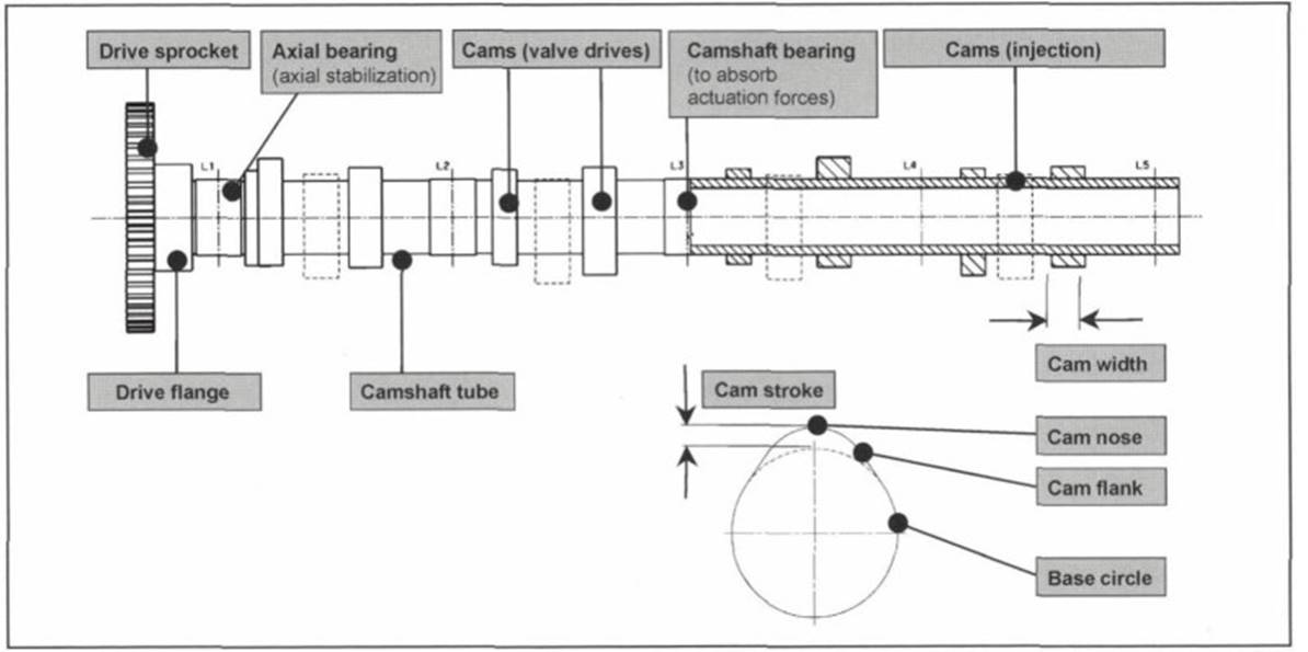
Fig. 7-212. Structure of a camshaft
The crankshaft is driven by a drive sprocket that is attached either permanently or detachably to the drive flange at the end of the camshaft. As an alternative to this arrangement, the second camshaft in DOHC engines may be driven by the first camshaft. In this case, the first camshaft is fitted with an additional driving wheel (usually a sprocket or gear).
Auxiliary units are driven with an additional driving flange or takeoff at the free end of the camshaft or, for example, by an eccentric or lift profile at some point along the camshaft. A trigger wheel (generating one or more pulses per revolution) may also be mounted on the camshaft in order to ascertain the angular position of a camshaft.
The cam comprises one section with a constant radius (base circle) and the lifting area (run-up and run-down ramps, cam flank, and cam nose). The difference between the base circle and the highest point on the cam represents the cam lift stroke, which is selected to be proportional to the desired kinematic valve stroke.
Systems with mechanical clearance adjustment faults in the cam’s base circle (deviations of the base circle from constant radius) have no effect on operational properties. A system with hydraulic valve play adjustment, by contrast, responds to every change in the base circle. Where there is a fault opposite the direction of movement, the hydraulic valve lifter compensates for this fault as valve play; in this case the valve stroke increases. If there is an error in the cam base circle in the lift direction, then the valve is already opened in the base circle segment because of the associated rise in force. This “pumping up” can, in extreme cases, result in complete loss of combustion chamber compression and engine failure.
Technologies and Materials. Camshafts made of cast iron are very widely used and differ in terms of the microstructure and hardness. Figure 7-213 provides an overview of the technologies and materials used.
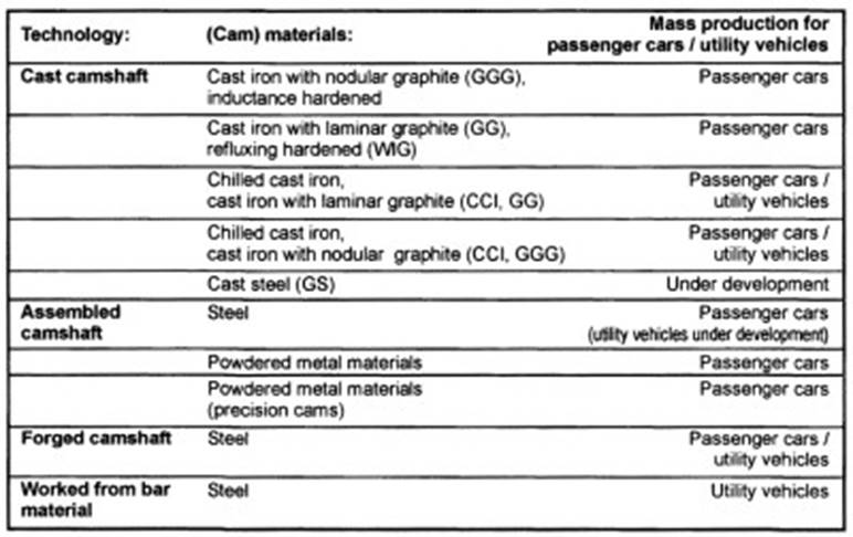
Fig. 7-213. Camshaft technologies and materials
Assembled camshafts are made up of individual components (tube, cams, drive flange, etc.) that have been assembled. The materials can thus be matched exactly to the particular requirements.
When demands are extreme, camshafts forged from steel or machined from solid material (bar material) are used. A new manufacturing technology, cast steel camshafts, is currently under development.
Cast Camshaft. A camshaft made of cast iron with nodular or laminar graphite is often the ideal tribologic match for sliding contact and low-load rolling contact in many applications. With proper alloying and closely defined hardening of the cams, tolerable pressure levels of well over 1000 MPa can be attained.
In the case of chilled cast iron the cam area is cooled quickly following casting to create a wear-resistant carbide structure (ledeburite) with great hardness and good tribologic compatibility. A gray casting with good machining properties is available for use in the core area and the camshaft bearing points, Fig. 7-214.
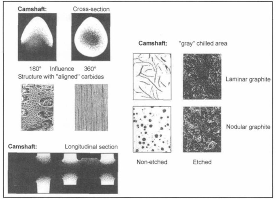
Fig. 7-214. Chilled cast iron in cross section
Assembled Camshaft. Serving as the basis for an assembled camshaft is a tube to which individual cams are attached by shrink fit, press fit, interior high-pressure forming, or a comparable joining process. It is possible to distinguish between camshafts in which the tube and all the attached components are present as finished parts when they are attached and require no further machining and those processes in which the camshaft following assembly is available as a rough component (either in whole or in part), which has to be ground like conventional (unitized) camshafts.
Steel or sintering material (powdered steel) is used for the cams.
Steel cams are normally forged as a rough part; the inner bore is then machined, and the cam is mounted on the tube. To attain the required materials properties, the cam can be hardened and tempered before or after attachment.
Using sintered material at rolling contact points makes it possible, since the cam geometry can be sintered more exactly than the required manufacturing tolerances, to build a camshaft that need not be further worked once the inside bore has been machined and the cam has been mounted on a tube with final geometry.
Figure 7-215 shows some examples of cam materials for assembled camshafts.
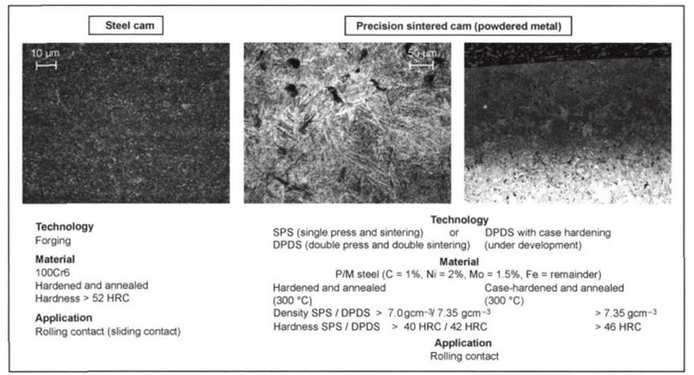
Fig. 7-215. Cam materials for assembled camshafts
A high-alloy, liquid-phase sintered, powdered-metal steel was developed for use as a sintering material for sliding contact.
Steel Camshaft. Used for almost all applications with rolling contact in utility vehicles and in many passenger cars are forged steel camshafts or steel camshafts that are machined from solid material. When there are high demands in terms of torsional and/or tensile strength, steel shafts also have to be used for sliding contact.
With the high tolerable pressure levels and the good mechanical properties of the material, these camshafts can be used for maximum demands, provided that correct tribologic mating materials are used.
Materials Properties and Recommended Matches. Figure 7-216 shows, for example, the spreads for torsional and tensile strengths for various cast materials. Various potential matches for rolling and sliding contact and the tolerable Hertzian pressures in each case are shown in Fig. 7-217 and in the summary of trends in Fig. 7-210.
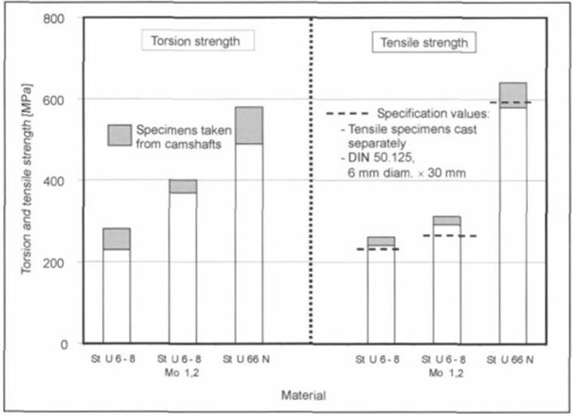
Fig. 7-216. Strength values for various casting materials
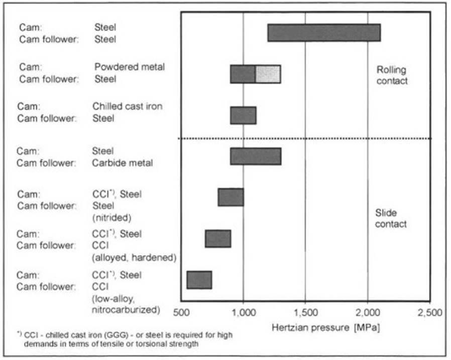
Fig. 7-217. Pairs of materials and Hertzian pressures

Fig. 7-218. Reducing masses in camshafts
Starting with the simplest gray cast camshaft, with cast tappets as the cam followers for sliding contact, it is possible to cover the entire range with the pairs of materials depicted, through to high-load rolling contact with cams and rollers made of roller bearing steel (100Cr6).
Date added: 2024-05-12; views: 1233;