Valve Guides. Requirements for Valve Guides
Valve guides, just like the valves and valve seat inserts, are essential components in the valve train. Consequently, annual demand is comparable to that for the mating components, coming to between 900 million to one billion units per year (see Fig. 7-152).
In terms of the materials, the market is divided into powdered metal, reformed brass, and cast iron qualities.
Requirements for Valve Guides. The function of the valve guide is to stabilize the reciprocating valve in such a way that it is always perfectly positioned at the sealing surface inside the valve seat insert. The tribologic system is formed by the valve stem and the valve guide. Lubrication occurs when motor oil seeps through the gap between the valve stem and the valve guide. In some materials, certain alloying additives and/or components in the microstructure contribute to lubrication.
Because of the increasingly stringent exhaust emission laws, it will become more important to reduce oil seepage rates in the future. Required here are combinations of materials that permit running dry, i.e., without additional lubricating oil. Increased abrasive or adhesive wear, particularly at the ends of the valve guides, will result in poorer performance and emission values for the engine. Adhesive wear can, in fact, cause seizure. As at the valve seat inserts, there are various influencing factors that have to be taken into account when engineering and using valve guides.
Loading on Valve Guides. The loads encountered inside the valve guide are reactions to forces that the valve stem introduces into the tribologic system represented by the valve guide and the valve itself; these forces tend to tip the valve.
They consist of the following:
- Friction action at the end of the valve (Fq)
- The lateral forces exerted by the valve spring (Ff)
- The standardized eccentric force on the end of the valve (Fn)
- The forces exerted by gases on the valve disk (Fgas)
The moments thus generated are neutralized by opposing forces at both ends of the valve guide. Figure 7-169 illustrates this equalization of forces.

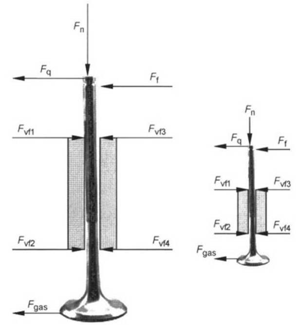
Fig. 7-169. Forces at the valve and valve guide
When running dry, the loading at the ends of the valve guides causes metal-to-metal contact with the valve stem. Oil inside the valve guide forms a hydrodynamic lubricating film as a result of the valve’s reciprocating motion; pressure is developed at the ends of the valve guide. This lubricating film separates the mating surfaces through to the point that the motion is reversed.
Then there is a brief period of direct contact between the surfaces’ solid bodies, which then reverts again from adhesive sliding to sliding action. In principle, the contact between the valve stem and the guide cycles continuously through the friction situations described in the so-called Stribeck curve, depending on the sliding velocity. The following items influence loading inside the valve guide:
(a) Valve train: The forces occurring at the ends of the valve guide vary, depending on the type of valve train that is used. Consequently, the lateral forces for rocker arm valve trains are as much as five times as great as those found in valve lifter designs. Figure 7-170 shows the typical cycle of lateral forces in a rocker arm valve train.
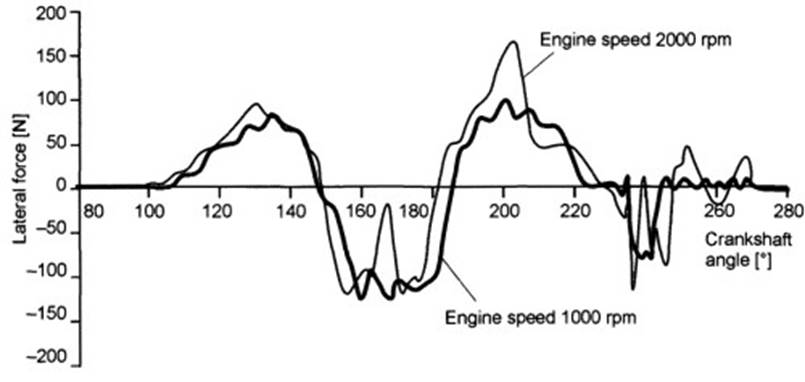
Fig. 7-170. Lateral forces at a valve guide, at varying speeds (engine driven, valve play 0.1 mm, valve guide play 45 µm, oil temperature 50°C, rocker arm valve train)
(b) Valve clearance: Dynamic processes in valve lifting induce additional forces (Fig. 7-171). Increasing valve clearance by 0.1 mm increases the lateral force by 22%.
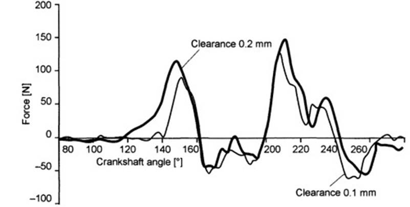
Fig. 7-171. Lateral forces at a valve guide, at varying clearances (engine driven, engine speed 1000 rpm, valve guide play 45 µm, oil temperature 60°C, rocker arm valve train)
(c) Valve stem seal: Creating a hydrodynamic lubricating film in the contact area between the valve stem and the valve guide requires both a sufficient quantity of oil and an adequate valve sliding velocity. This is achieved with valve stem seals that allow defined volumes of oil to pass through the stem sealing area. Normal values lie in a range of from 0.007 to 0.1 cm3/10 h.
When using turbochargers or engine braking in utility vehicles, the pressure situation on the port side of the valve guide can fluctuate, thus influencing the oil seepage rate. Investigations have revealed that gauge pressure of 0.8 bar on the port side can cause the oil to be forced out of the valve guide, resulting in insufficient lubrication with increased wear and the potential for seizure. Specially engineered shapes for the valve stem seals can eliminate this problem.
(d) Valve guide clearance: The valve guide is responsible for exact positioning of the valve in the seat at the valve seat insert. To ensure that this task is fulfilled, the valve guide bore and the outside diameter of the valve stem have to be sized to match one another, always striving to achieve the smallest possible amount of play at the valve guide. In addition to improved heat transfer, the hazard of the valve’s tipping is reduced.
Moreover, this geometric matching of the mating components supports the establishment of the hydrodynamic lubricating film. The lower limits for the difference between the diameters are determined by the divergent coefficients of thermal expansion for the guide and the valve stem. Figure 7-172 provides some basic valves for valve guide clearances.
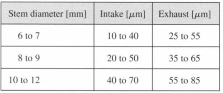
Fig. 7-172. Basic valves for valve guide clearance
(e) Valve: As the component mating with the valve guide, the valve itself has a critical influence on wear phenomena by two factors.
(1) The heat applied via the valve stem: Theoretical calculations assume that some 10% to 25% of all the heat impinging on the valve is dissipated through the valve guide. This effect depends on the thermal conductivity of the valve stem material (12 to 21 W/mK), while the engineering design of the valve is also of decisive importance. Hollow valves filled with liquid sodium serve to lower (by between 80 and 150 K) the temperature at the critical curved area at the back of the valve head.
Cooling is achieved by the liquid sodium inside the valve transporting heat from the head to the stem area. The higher thermal loading thus imposed upon the guide makes particular demands on the material and system tuning.
(2) The material for the stem: Distinction is made here among the following groups of materials: Ferrous alloys: Valve stems are made up primarily of martensitic or austenitic qualities. Surface roughness is Ra < 0.4. The surface finish can be improved by chrome plating or nitriding. Typical thickness values for chrome plating are from 3 to 15 μm and from 10 to 30 μm where nitriding is employed. Post-treatment of the finished surfaces by polishing is indispensable since residues from the production process (chrome nodules or nitride needles) have to be removed completely to prevent increased wear at the valve guides. The target value for surface roughness is Ra < 0.2.
Nickel-based alloys: This group of materials is used, in particular, wherever exhaust valves are exposed to high thermal and mechanical loading. In general, this group of materials is known as “nimonic” alloys. When compared with the ferrous alloys, there are no particular factors of interest regarding the tribologic system comprising the valve stem and valve guide.
Lightweight metal alloys: To reduce the masses in motion in the valve train, current research activities are focussing on the use of titanium and aluminum alloys for valves.
Nonmetallic materials: The types of ceramic materials now in use exhibit good wear-resistance properties. No special adaptive measures are required when such stems are used in conjunction with conventional valve guide materials. The reason is found in the excellent surface quality of the ceramic valves.
Date added: 2024-05-12; views: 978;