Valve Seat Inserts. Demands Made on Valve Seat Inserts
Introduction. Valve seat inserts and valve guides are important components within the valve train and are essential to perfect ignition and combustion within the cylinder. Together with the valve, these components must ensure complete sealing of the combustion chamber so that the required compression and ignition pressures can be generated inside the cylinder. Excessive wear causes changes in the combustion parameters and thus degrades engine performance and emission data.
Figure 7-151 shows a drive train with hydraulic valve lifters and an overhead camshaft. The valve seat and the valve guide are components that are typically produced in large numbers. Figure 7-152 provides a survey of the passenger car engines built in 1998 and 1999.
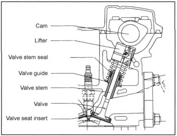
Fig. 7-151. Drive train with hydraulic valve lifters and overhead camshaft
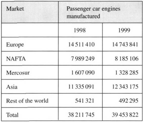
Fig. 7-152. Worldwide production of vehicular engines
This represents demand for between 900 million and one billion components. Around the world 13 companies manufacture valve seat inserts, and they can be subdivided by materials groups into cast materials and powdered metal materials, which account for a 90% share of the market.
Demands Made on Valve Seat Inserts. More than 99% of all aluminum cylinder heads are fitted with separate valve seat inserts because the properties of aluminum and its alloys are not adequate for making up valve seats. The valve seat insert, together with the valve itself, forms a tribologic system that has to ensure sealing capacity even after several million operating cycles.
Thus, specifications for modern engines mandate maintenance- free operation of the mechanical valve train without compensation for clearance, for mileage of up to 300 000 km (<2 μm/1000 km). All this takes place in an extremely demanding operating setting. The major factors influencing wear at valve seat inserts are discussed below.
Loading on Valve Seat Inserts. Varying loads are encountered in the valve seat contact area, depending on the specific engine design. The method used for adding fuel, the compression ratio, the ignition pressure, and the associated specific forces, as well as the temperatures prevailing in the contact area, all vitally influence wear and deformation in the tribologic system comprising the valve and valve seat insert. The wear factors that thus arise are summarized below.
a) Mechanical loading at the valve seat area. This loading comprises the spring preload (Ff), the valve’s closing force (FB), and the pressure exerted by combustion (Fp). Figure 7-153 provides a survey of the percentages for the various types of loading imposed on the valve seat in an overhead camshaft engine.
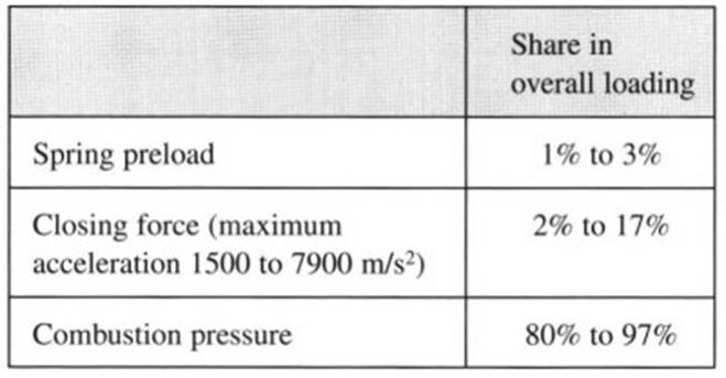
Fig. 7-153. Distribution of loading at valve seat
This loading is subdivided into forces exerted perpendicular and parallel to the seating surface; the split varies with the valve seat angle. The parallel forces are the primary factor in wear and deformation at the valve seat. The sizes of the forces and the distribution of the loads they generate depend on the engine design and the current operating status (e.g., electromagnetic valve operation, engine braking).
b) Dynamic loads exerted on the valve seat due to valve motion relative to the valve seat insert. One portion of the motion is the rotation of the valve. This depends on engine speed and, in valves actuated conventionally, may be as much as 10 rpm or, when using the so-called Rotocaps, up to 45 rpm.
This motion is desirable since, on the one hand, it ensures uniform valve temperature and, on the other hand, it has a cleaning effect on the valve seat. A further dynamic load on the seat results from valve disk deflection, which occurs automatically when the pressure in the combustion chamber impinges upon the valve head. This effect is reinforced by a differential between the contact angles at the valve and valve seat, between 0.5° and 1°, which is referred to as the differential angle (Fig. 7-154).
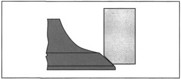
Fig. 7-154. Differential angle at the valve
In this way, a narrower seat diameter and thus higher pressure at the sealing surface, with enhanced sealing effect, is achieved where ignition pressures are low. When the pressure is increased, the bearing portion of the contact surface increases because of bending at the valve disk, resulting in reduced surface pressure at the valve seat.
c) Lubricating the seat contact area. The wear rates at the tribologic system formed by the valve and valve seat insert are greatly influenced by intermediate lubricating layers. The effects at the intake and exhaust sides differ, depending on the composition of the fuel mixture. Figure 7-155 compares the influence of the types of fuels on wear between the valve and the valve seat insert.
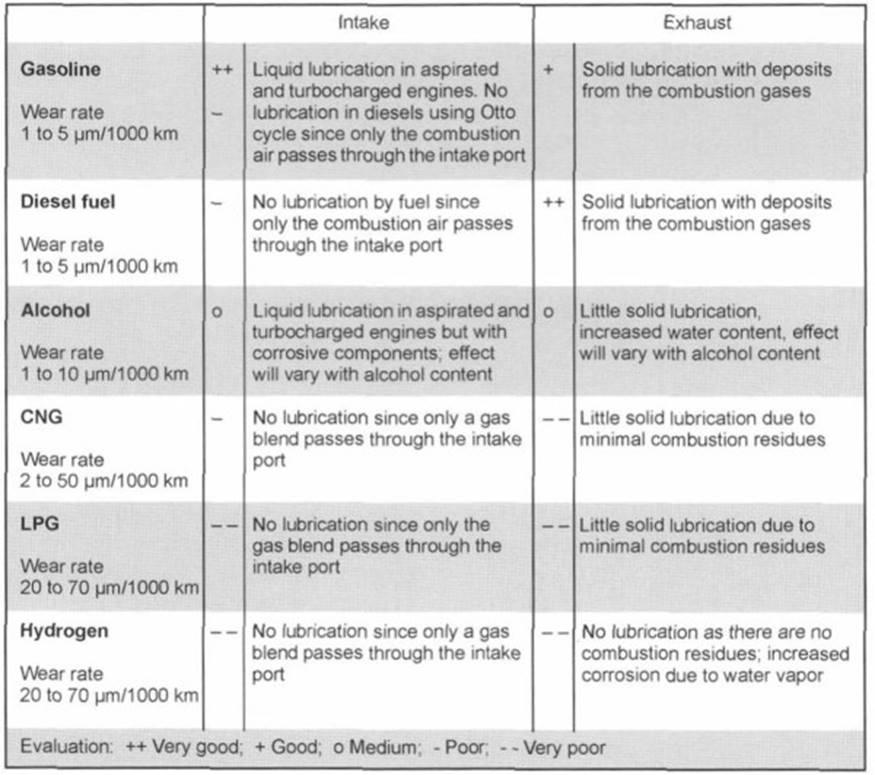
Fig. 7-155. Influence of type of fuel on wearing action at the valve and valve seat insert
These effects are essentially subordinated by further, superimposed phenomena. Mentioned here, in particular, is the potential enrichment of the mix resulting from introducing crankcase vapors at the intake. Additionally, oily components can pass through the valve stem seal and along the valve stem to the seat contact area.
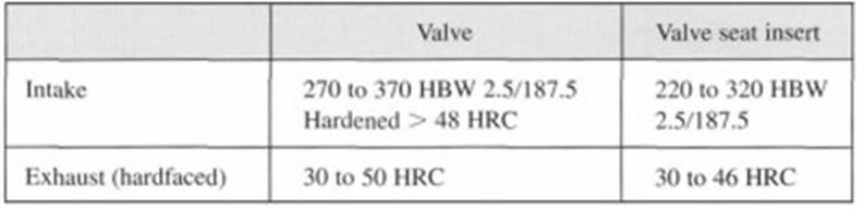
Fig. 7-156. Comparison of hardness for the valve and the valve seat insert
d) The partner in wear—the valve. When designing the valve train, it is important to ensure that the valve contact surface is harder than the mating surface at the valve seat insert. This is necessary to achieve proper distribution of wear—one-third at the valve and two- thirds at the valve seat insert. This wear ratio is necessary since, in the opposite case, the valve disk could gradually be weakened. Consequently, the valve could slip into the valve seat, causing engine damage. Typical hardness values are summarized in Fig. 7-156.
Valve Seat Inserts. Materials and Their Properties Materials
Casting alloys. Various production methods, including die or sand casting and centrifugal casting, are employed to form components from these alloys.
The components are manufactured as follows:
- Cast iron: Low-alloyed gray casting material is used at both the intake and the exhaust ports for engines developing low internal loading. The high share of free graphite in the material ensures good emergency (dry) running properties. The material’s properties can be further improved by heat treatment, e.g., to enhance ductility, which is necessary when using titanium valves. Austenitic cast iron is used to harmonize with the coefficients of thermal expansion found in aluminum cylinder heads. Increasing the amount of carbide increases wear resistance in this material.
- Martensitic steel castings: These materials are based on tool steels and rust-free martensitic steels. They are generally employed as hardened qualities for intake and exhaust valve seat inserts in utility vehicle engines involving moderate and high loading, at temperatures of up to about 600°C. Good corrosion resistance is achieved by adding chrome.
- Nonferrous alloys: This group of materials comprises high-alloy nickel- or cobalt-based alloys. Such alloys are used particularly at the exhaust side in engines where high loading occurs. Characteristic of this group of materials is the high shares of carbides and the inter- metallic phases. Excellent high-temperature characteristics, capable of handling up to 875°C are attained. Disadvantageous are the high costs for the materials, their low thermal conductivity, and the difficulties in machining. In high-performance engines (racing and Formula 1) copper-based alloys doped with beryllium are used because of their great thermal conductivity.
Powdered metal materials: Here a powder mixture is compacted at pressure of up to 900 MPa inside a mold that is close to the final contours. The resulting blanks, the so-called green bodies (powder preforms), are sintered at high temperatures (1000 to 1200°C for ferrous alloys) and then subjected to heat treatment. Mechanical machining—turning and polishing—concludes the production process. Additional manufacturing steps may, however, be required, depending on the type of material used. The goal of modern powdered metal development is to keep down the number of manufacturing steps in the interest of achieving major cost savings.
Powdered metal materials are subdivided into several groups:
- Low-alloy steels: Low-alloy steels are used primarily for intake valve seat inserts in gasoline engines. These materials are based on a Fe-Cu-C system. The structure is ferritic/pearlitic in nature, with a share of cementite. Small amounts of nickel or molybdenum are used to improve wear properties. Solid lubricants (such as MnS, Pb, MoS2, CaF2, or graphite) are often used to improve amenability to machining by cutting (free-cutting properties). Overall, the amount of alloying material is less than 5%.
- Medium-alloy steels: These materials are generally used as the valve seat inserts for gasoline engines and at both the intake and the exhaust ports in diesel engines. This group of materials is the one most widely used and provides a broad range of variants, of which the three most common groups are worthy of mention.
In the martensitic steels the microstructure is essentially a martensitic tempered structure with finely divided carbides, solid lubricants, and, if appropriate, hard metal phases (intermetallic phases of great hardness and temperature resistance such as Co-Mo- Cr-Si Laves phases and Co-Cr-W-C phases). Highspeed steels derive their superior wear strength from a martensitic matrix with a fine distribution of specially formulated M6C or MC type carbides, which can be made by alloying elements such as Cr, W, V, Mo, and/or Si.
Taking the standard high-speed steel alloys (such as М2, M4, and M35) as the basis and using alloying technology modifications, such as diluting with iron powder, adding solid lubricants, or adding other hard-phase elements, finally culminate in the valve seat material. In contrast to the other two materials groups, bainitic steels do not have any tempered structure but instead a thermally more stable bainitic basic structure. The addition of solid lubricants, carbide-forming agents, and hard phases in combination with the fundamental structure produces good wearing properties when hot. Typical alloying elements include Co, Ni, and Mo.
The medium-alloyed steel groups can also be purchased as copper-infiltrated qualities. Here the open volume between the pores in the sintered body is filled with liquid copper during the sintering process. The advantage of this alloy, in addition to improved heat conductivity, is found in better machinability.
- High-alloy steels: This group includes martensitic and austenitic materials. They are used in engines with higher demands for resistance to high-temperature oxidation and corrosion. Typical alloying elements include Ni, Cr, and Co. Because of the high alloying element content, these materials are very costly when compared with the other materials groups. It is for this reason that dual-layer technology is often used in which the valve seat insert is made of two layers of different materials—a high-alloy material at the valve seat and a low-alloy material facing the port.
- Nonferrous alloys: The basic Ni and Co alloys, in contrast to the casting alloys, are encountered only very seldom in powdered metal technology. Copper- based materials are particularly interesting for racing applications. One objective of modern materials development efforts is to identify substitutes for toxic beryllium as an alloying element. Adding ceramic particles (such as Al203) has already made it possible to achieve wear values comparable to those in the standard applications.
Properties. Valve seat insert materials must exhibit certain properties to satisfy the material technology requirements. The key properties are enumerated below:
- Hot hardness: A material’s hardness generally corresponds to its wear resistance. For this reason hot hardness is used as an indicator of a material’s wear resistance at elevated temperatures. Severe drops in hardness at rising temperatures may point to potential temperature limits for a given material (Fig. 7-157).
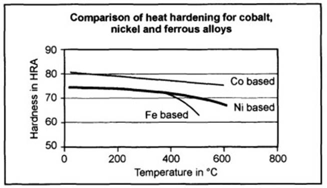
Fig. 7-157. Hot hardness comparison
Structural stability at elevated temperatures identifies changes in the material due to the influence of heat. Figure 7-158 summarizes various effects. One must assume that there are diffusion-related changes, in particular, for materials with tempered structures when they are subjected to thermal stress.
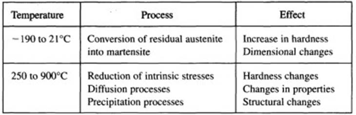
Fig. 7-158. Effects due to thermal loading
- Coefficient of thermal expansion: The coefficients of thermal expansion for valve seat inserts and cylinder head materials are of considerable significance when mounting the inserts in the cylinder head with a press fit. It is beneficial if the materials used for both items exhibit similar coefficients of thermal expansion. If this is not the case, then a reduction in the holding force may occur when the system heats up (which is the case when combining ferrous valve seat inserts and aluminum cylinder heads). This can cause the valve seat to be dislodged from the cylinder head bore and result in damage to or destruction of the engine. Figure 7-159 shows typical values for coefficients of thermal expansion.
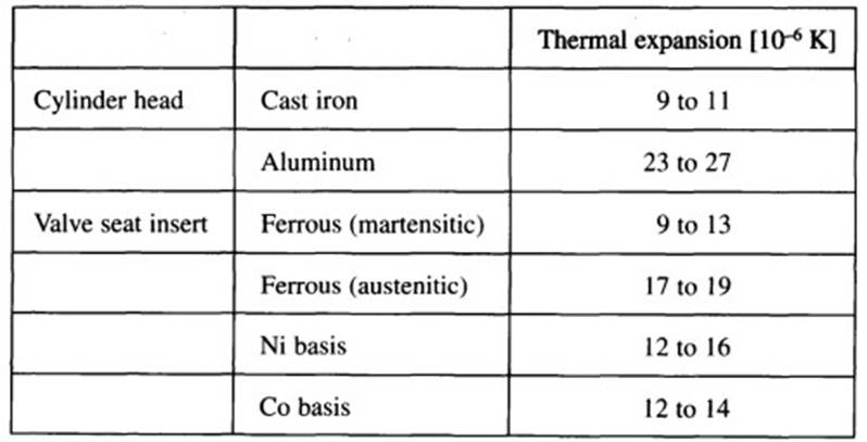
Fig. 7-159. Coefficients of thermal expansion
- Thermal conductivity: To keep valve temperature within reasonable limits it is necessary to ensure good transfer of heat from the valve disk, via the valve seat insert, to the cylinder head. This is achieved, in addition to engineering good heat transmission interfaces, by selecting materials with high thermal conductivity. Figure 7-160 depicts the theoretical heat flows at the valve.
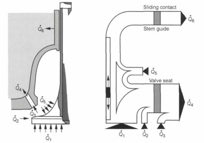
Fig. 7-160. Thermal flow at the valve
Theoretical calculations have revealed that an increase in conductivity from 20 to 40 W/mK reduces the operating temperature at the valve seat insert by 50 К and that at the valve by 30 K. Measurements in various engines have confirmed this reduction in valve head temperature. One method commonly used to achieve these values is to infiltrate the medium-alloyed materials used on the exhaust side with copper.
Figure 7-161 summarizes some representative values. When engineering the cylinder head, one must take into account the fact that the increased injection of heat into the aluminum comprising the cylinder head around high-conductivity valve seat inserts causes a loss of strength in the aluminum. Fissuring in the web area is the result of this type of thermal overloading.
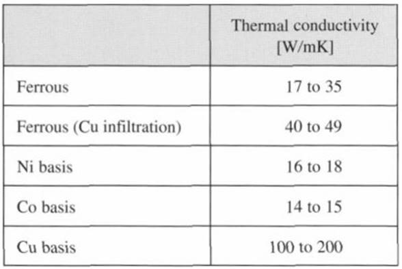
Fig. 7-161. Thermal conductivity
- Density: In order to keep the stresses on materials as low as possible, materials with higher density are favorable because of their higher specific contact area at any given loading level. This also keeps the notching effect of the pores from initiating fatigue, culminating in material breaking away. In contrast to cast valve seat inserts, one must expect a certain volume of pores in powdered metal products.
- Resistance to oxidation and corrosion: Because of the extreme operating situation, valve seat inserts must be able to withstand corrosion and oxidation resulting from exposure to the hot exhaust gases. This can be achieved either with the chemical composition of the material or by a carefully defined passivation of the component’s surfaces by preoxidation, for instance.
Wear resistance: The following wear-inducing mechanisms are effective here:
- Adhesion: Local microwelds with subsequent failure at the contact points. Material is transferred from one interface surface to the other, and pitting will take place.
- Abrasion: Material removal due to grinding and cutting mechanisms in the microscopic range. Material transfer is found to only a limited extent.
- Oxidation: Forming brittle, loose oxide layers, which will spall off under load.
- Corrosion: The formation of reaction phases, such as the nickel-sulfur eutectic with its low melting temperature, can cause high nickel content material to weaken and break away.
- Machining properties: Good machining properties are an important criterion when evaluating materials for valve seat inserts since the final machining of the valve seat has to be effected after the insert has been mounted, which is because of the close tolerances for the cylinder and the valve seat insert. The nature of the microstructure, the highest possible density, and the addition of solid lubricants can have a positive effect on tool lives.
Date added: 2024-05-12; views: 948;