Designing Cam Profiles
The progress of the valve stroke required, which is usually specified by the engine manufacturer, is a compromise for ideal filling across the entire speed range (high moment in the lower and medium speed ranges and at the same time high maximum power output).
Here the peripheral geometric conditions such as valve diameter, valve stroke, and valve clearance to the piston at TDC are most important on one hand, while the demands in terms of functioning and manufacturing (such as jerk-free transitions in the entire valve stroke cycle or thermal loading of the exhaust valve while opening) are the most important parameters, on the other hand.
This specified and targeted advance for the valve stroke, depending on the type of valve train and its kinematics, is recalculated to form a cam profile matched to the cam follower.
If mechanical valve clearance adjustment is implemented, there is always some play in the total system between the cam and the valve. This play causes inconsistency at the start of the stroke and thus always creates a sudden load. During the closing cycle there is also a “bump” because the valve contacts the valve seat before the cam stroke is completed. In order to limit the seating velocities and sudden accelerations for the valve train components involved, it is necessary to provide the appropriate opening and closing ramps.
Variances in the valve stroke occur in systems with mechanical valve clearance compensation, the extent depending on wear and temperature; valve overlap also varies (phase during which the intake and exhaust valves are both open). In valve trains incorporating hydraulic valve lifters, these ramps are far flatter, Fig. 7-220; the valve stroke and overlap are nearly constant.

Fig. 7-220. Valve stroke, speed, and acceleration plotted against the cam angle for a roller cam follower valve train with hydraulic valve lifters
An important criterion for design is Hertzian pressure. This indicator value describes the compressive load on the mating components. Using the maximum tolerable Hertzian pressure allows us to preselect potential materials for cams and cam followers. The dynamics calculation usually shows, in comparison with the basic kinematic design, more realistic values for the location and size of maximum pressure values, Fig. 7-221.
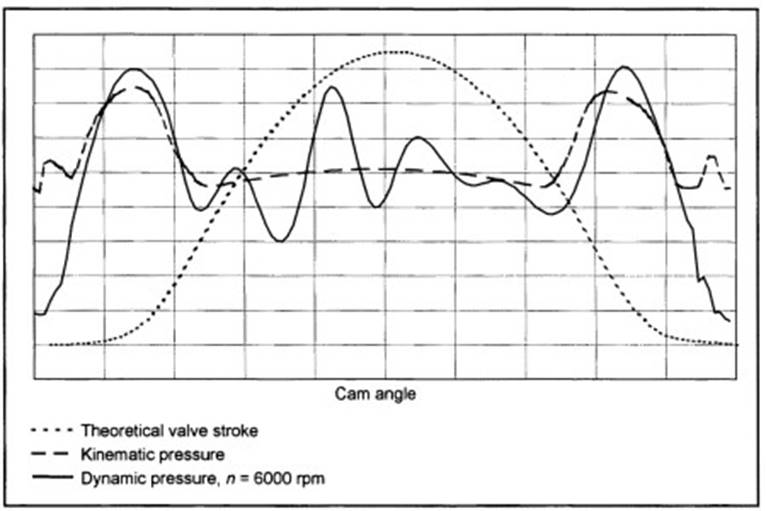
Fig. 7-221. Theoretical valve stroke and Hertzian pressure (kinematic and dynamic) for a roller cam follower drive train with hydraulic valve lifters
When a roller is used as the cam follower (roller tappet, roller lever) there are often concave radii in the flanks of the cams. Here it is necessary to consider manufacturing limitations in reference to grinding. It may be necessary under certain circumstances to accept deviations from the specified valve stroke curve. When using sintered cams, the outer contours of which require no additional machining, any concave radius can be realized (at least in principle).
When using an assembled camshaft, it is necessary to pay attention to the moments that are transferred, depending on the system, as a decisive magnitude. During engineering, one must ensure that the maximum dynamic moments can be transferred with the required degree of confidence.
Date added: 2024-05-31; views: 738;