Kinematics and Dynamics Calculation
In the kinematic (quasistatic) calculation, the moving masses in the individual valve train are reduced to one single mass and one spring (the valve spring). A targeted motion (corresponding to the progression of the valve stroke) is imposed upon this individual mass. The mass and spring forces are considered in this way; additional outside forces such as gas forces coming into play when the exhaust valve is opened can be taken into account.
The most important results of kinematic calculations include the hydrodynamically effective speed for sliding contact, roller speed for rolling contact, and/or Hertzian pressures between the cam and its follower (as well as bearing loads for the valve train components), loading, and relative motion of the driving element at the end of the valve shaft or a valve link (e.g., valve finger radius, elephant foot, etc.).
The hydrodynamically effective speed (total speed, lubrication index) is a measure of the cohesion of the lubricating film between the components in contact, Fig. 7-222. In the case of sliding contact there are two “zero intersections” (change of sign) in this curve during each cam revolution. Since at that particular moment the load-bearing capacity of the lubricating film collapses, the risk of wear can be reduced by suitable design.
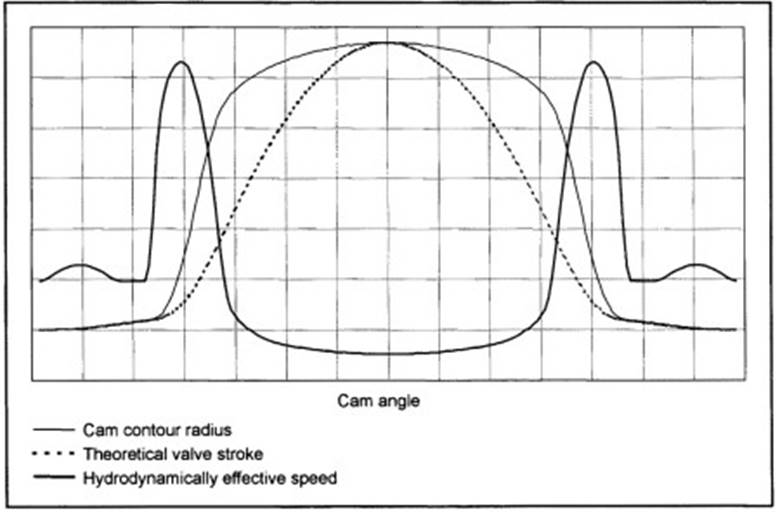
Fig. 7-222. Cam contour, theoretical valve stroke, and hydrodynamically effective speed plotted against the cam angle at contact between cam and flat tappet
When there is rolling contact with roller bearings (such as a needle bearing in the case of a roller cam follower), it is possible to analyze the service life (taking into account various loading populations).
Dynamics Calculations. Calculations of the dynamics supply a far more accurate image of real system behavior than does the relatively simple kinematics model. Accordingly, greater effort is required for modeling. Multibody simulation is the tool used for dynamics calculations.
Common to all such programs is that the mechanical systems being assessed are broken down into individual masses and that they are then coupled one with another by means of spring and damping elements corresponding to the stiffness of the components and their damping properties. In addition to integrating hydraulic subsystems (hydraulic valve lifters) into the simulation, it is also possible to use the results from FEM calculations, e.g., force- or path-dependent stiffnesses for components.
The degree of detail for the dynamics calculation is virtually as desired and is limited only by the ratio of benefit to effort.
With all these elements and peripheral conditions, there arises a model capable of oscillation that, in addition to the stiffness, also depicts the eigen frequencies for the system being observed. The output depicts the motions of the individual components and the forces and pressures effective upon them.
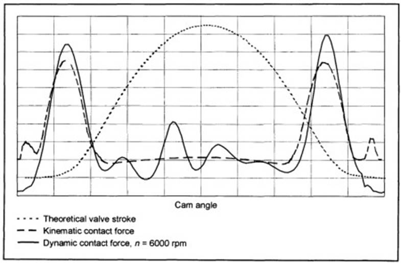
Fig. 7-223. Theoretical valve stroke, kinematic contact force, and dynamic contact force plotted against the cam angle for a rocker arm valve train with hydraulic valve lifters
One sees in Fig. 7-223 that the force between the cam and roller deviates distinctly from the progress determined kinematically, which is the result of the oscillations superimposed on the targeted motion. Particularly in valve trains with hydraulic clearance compensation, loss of contact can result in grave problems (pumping up the hydraulic valve lifters).
A dynamic analysis of the valve train can identify critical components right in the engineering stage (long before parts are developed for measurements and engine operation) and thus shorten the development process considerably.
Date added: 2024-05-31; views: 746;