Synchronous Belt Drive System
The most important demand placed on the toothed belt system is synchronizing the camshaft over the engine’s entire lifetime. This is an important criterion for maintaining emission values even after extended periods in service. With proper selection of the materials for the belt, the use of an automatic tensioning system, and the use of optimized system dynamics, stretch in the synchronous belt can be kept to less than 0.1% of belt length. In four-cylinder engines this represents a timing deviation of from 1 to 1.5 crankshaft degrees.
The usual requirements in engine building continue to apply, regarding engine life (currently 240 000 km), temperatures of about 120°C, the smallest possible build size, and minimum weight.
Bothersome noises generated by the belt drive are not acceptable.
Design Criteria. Complex synchronous drives are engineered with computer support. A survey of the most important parameters considered in the design and some general design criteria is provided here.
The profile of the sprocket has to be selected to match the diameter. The effective diameter is the product of the number of teeth and the pitch; the outside diameter of the sprocket is reduced by a value corresponding to the pitch line distance (Fig. 7-241).
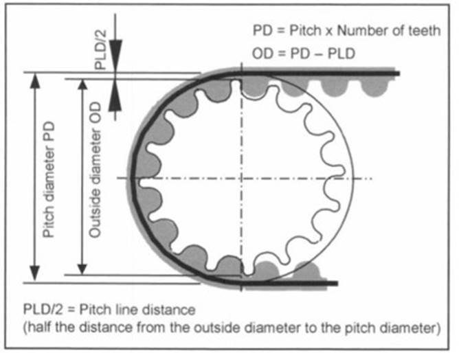
Fig. 7-241. Key values for the sprocket
The design of complex synchronous belt drives is computer supported. The most important parameters in design as well as a few general design criteria are discussed here. Important input data include the arrangement of the components, i.e., the drive configuration, torque development at the components, and the dynamic circumferential forces calculated from them, along with the data for the belt itself.
With these data at hand, it is possible to calculate and optimize not only the span lengths and wrap angles, but also the belt’s lifetime in reference to various failure modes. The dynamic forces and oscillations are used to calculate in the same way the other components in the system, such as the design of the reversing pulleys and the idler pulleys.
Given below are a few general design criteria that must be observed in synchronous belt systems in order to engineer a functional system that will achieve the 240 000 km lifetime required today:
Periodic Tooth Engagement. Periodic tooth engagement means that a given tooth always engages with the same sprocket groove. This is to be avoided so as to preclude irregular belt wear and the belt damage that it may cause. The appearance of periodicity is calculated as follows:
X.nnn = Number of teeth at the belt
Number of teeth at the sprocket
Here the following values for X.nnn are to be avoided:
X.nnn = X.0, X.5 (must in all cases be avoided)
X.nnn = X.25, Х.ЗЗЗ, X.666, X.75 (ought to be avoided)
Span Lengths. In order to avoid resonance-induced noise at idle, unsupported span lengths should not lie in a range of from 75 to 130 mm.
Minimum Diameters for Sprockets and Deflector Pulleys
Pitch 9.525 mm 18 teeth (54.57 mm diam.)
Pitch 8,00 mm 21 teeth (53.48 mm diam.)
Smooth deflector pulleys 52 mm diam.
Axial Guidance. A synchronous belt has to be guided on at least one sprocket by flanges to keep the belt from wandering out of alignment. As a rule, guide flanges for the belt are located at the crankshaft (driving) sprocket. In this case, the crankshaft damper often serves as the forward flange. The rear flange is attached to or integrated into the crankshaft sprocket.
Additional flanges may be required in complex, multivalve trains, depending on the number of sprockets and deflector pulleys. In these cases, it is advisable to locate the flanges at sprockets and not at deflector pulleys. In general, it is important to ensure that sprockets with flanges are aligned exactly with the other pulleys and sprockets to avoid deflecting the belt from its prescribed path.
Sprockets and pulleys with just a single flange or without a flange are made wider than the belt itself in order to ensure that the belt runs stably on the sprocket or pulley. The width of the sprockets and the geometric design of the axial guide flanges are depicted in Fig. 7-242.

Fig. 7-242. Sprocket width and belt guidance
Belt Tensioning Systems. Fixed Tensioning Pulleys. In the past, tensioning pulleys were always fixed. Deflection pulleys mounted on an eccentric were most often used (Fig. 7-243). Preload was set mechanically on the line and was checked with suitable measurement instruments (span frequency measurement). One disadvantage for fixed tensioning pulleys is the increase in tension that results from the greater expansion of the engine in comparison to belts when the engine heats up. Another problem is that they cannot compensate for the loss of belt tension through the service life due to stretch and wear.
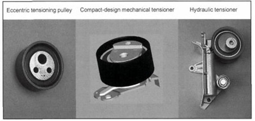
Fig. 7-243. Belt tensioning systems
Automatic Tensioner Pulleys. Because of the drawbacks associated with fixed tensioning pulleys and because of the increased dynamic forces in camshaft drives, accompanied at the same time by increased expectations regarding lifetime, automatic tensioning idlers are used to a greater extent. This technology compensates both for the temperature-related rise in tension and for belt stretch. It also keeps constant the high tension required for dependable operation at high engine dynamics.
The most widely used is the mechanical, friction-damped, compact-design tensioner. Hydraulic tensioning pulleys are used in some applications where very high dynamic forces are found in the belt drive system. With their asymmetrical damping they exhibit very good damping properties even at low preload values.
Date added: 2024-05-31; views: 752;